Speed 400
Cloudster Project
Sue and I spent a lot of this past
weekend decorating our for Christmas. It is a little early, but we are
flying down to Houston to spend Thanksgiving with Sue's son (Rick and wife
Andrea) and we wanted them up when we return on Saturday. With Sue still
recovering from her broken shoulder, our neighbor Donald Thompson was kind
enough to come over Saturday morning and help me with getting the 28 boxes
of decorations down out of the attic (I handed the boxes down
from the attic and Don stacked them on the garage floor for me).
The picture below shows our decorated Christmas tree that we put up in
front of the bay window in the "President's Room" (the named given to this
room by my dad before his passing).

I did
find some time to work on the Cloudster's landing gear Sunday afternoon.
After careful review of both the Cleveland and Jim Adams Cloudster plans, I
could not find a landing gear wire size called out nor a true view of the
wire landing gear layout. So a little reconstruction work had to be done.
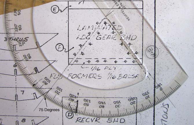
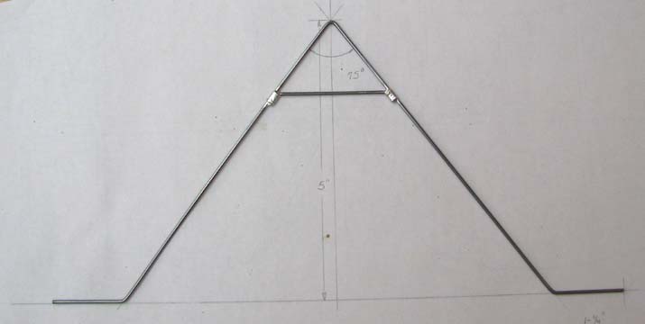
1/16" diameter piano wire was selected for the landing gear. On the Jim
Adams plans, the apex angle of the landing gear wire measures 75 degrees as
shown below.
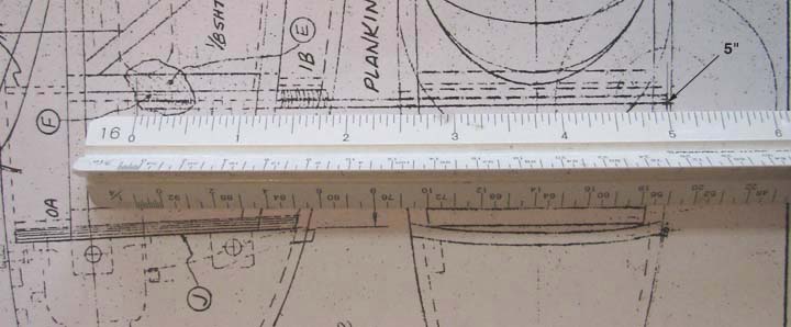
Also
on the Jim Adams plans, the vertical distance from the top of the apex angle
to landing gear axle measures 5" as shown below.
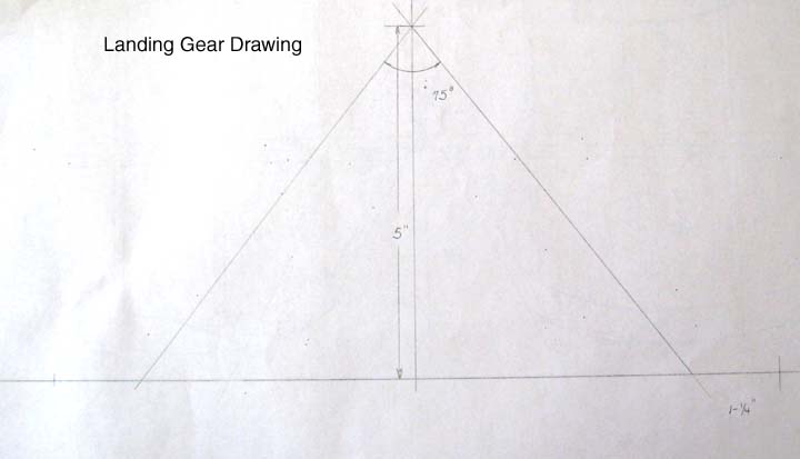
Given the 75 degree apex angle
and the 5" vertical distance, a true view of the wire landing gear drawing
can be laid out as shown below.
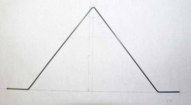
The landing gear was bent up out
of 1/16" piano wire as shown below.
Then the cross brace was made out
of 1/16" piano wire. It was positioned, wrapped with small brass wire, and
soldered in place as shown below.
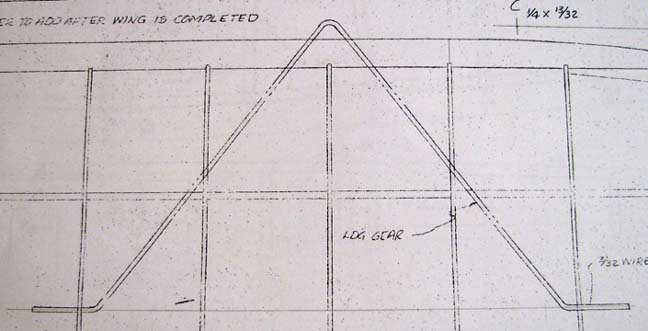
Did you ever look and look for
something and then later discover it is right in front of you? Well, after I
finished recreating the landing gear drawing, bending up the wire landing
gear and cross brace, and soldering it in place, I discovered that the
landing gear wire size and drawing was right there on the left wing drawing
shown below----Well DUH! The plan call out is for 3/32" landing gear wire
and the vertical height of the drawing was 4-3/4", which by the way
disagrees with the 5" shown on the plan's fuselage drawing shown above.
Since there is very little
difference in the landing gear drawings and the one I have already made is
lighter, I am going forward with it. I am going to look into making the
landing gear removable without having to much of a weight penalty. However,
this may not be possible, but that is the subject of a later
report......................................Tandy