Speed 400
Cloudster Project
Before starting work on
recessing leading edge, it is instructive to measure and compare the "as
built" overall vertical rise of each wing tip with the design value while
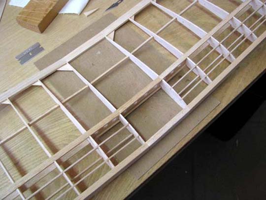
the temporary leading edge is still in place. The wing's inner panel end R1
rib replacements were glued in place, including the portion all the way
forward to the temporary leading edge as shown below. Notice that the three
turbulator spars are extend to these end R1 ribs as well and the trailing
edge dihedral joint was reinforced with two larger 1/16" gussets (0.6" on a
side) as shown below.
The design value of the wing's
vertical rise at the tip can be calculated from Report No. 33 as follows:
Design Vertical Rise = Hi' + Lt X Sin(J)
Design Vertical Rise = 1.257 +
12.027 X Sin(20.458) = 5.461"
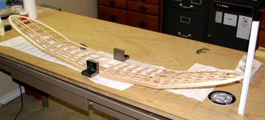
Now to measure the vertical
rise, the wing center section's leading and trailing edges were firmly
weighted down to the work table with two square steel blocks as shown below.
Then a triangular scale also shown below was used to measure the wing tip
vertical rise off of the work table.
The vertical rise measurement of
the lower edge of the left wing tip off the work table, as viewed from the
front leading edge, is 4-15/16" as seen below.
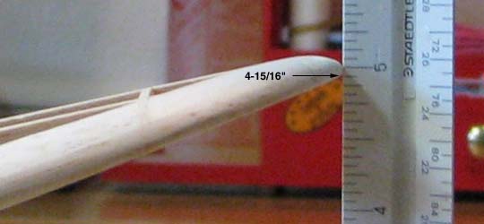
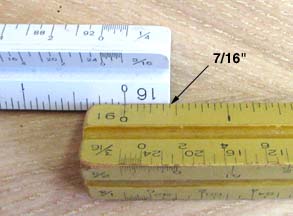
This however is not the true
measurement because there is a 7/16" (0.438") blank section at the end of
the scale as shown below. The true measurement is (4.938+0.438) = 5.376".
Therefore, left wing tip rise is slightly under the design value by
5.376-5.461 = -0.085", which is only a 1.6% overall error.
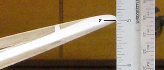
The vertical rise measurement of
the lower edge of the right wing tip off the work table, as viewed from the
trailing leading edge, is 5" as seen below, which is 5+0.438 = 5.438".
The right wing tip rise is slightly under the design value by 5.438-5.461 =
-0.023", which is only a 0.4% overall error.
These errors are well within
practical building tolerances for balsa. I am pleased and probably very
lucky that these errors turned out to be so
small........................Tandy