Speed 400 Cloudster Project
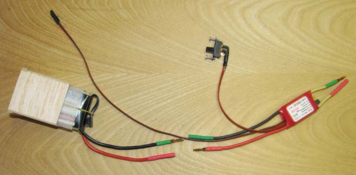
I began the day by soldering the polarized
connectors to the red and black wires on the Li-Po battery and the
corresponding red and black wires on the ESC as shown below. The battery in
its box was successfully installed in the fuselage through the opening in
the top of the cabin and the battery connected to the ESC a total of three
times. Based on this exercise, it was concluded that a hatch opening on the
bottom of the fuselage is not necessary.
The next task was to install the antenna guides for the two FASST
receiver antennae. I want to restate Futaba's three antenna requirements to
"maximize" the 2.4 GHz receiver's reception
performance. They are as follows:
(1) The two antennae are to be 90 degrees to each other.
(2) The locations of the two antennae are to be as far apart as practical in
the model's fuselage.
(3) The two antennae are to lie in different planes.
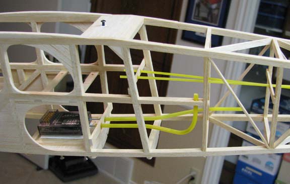
I used the standard Sullivan Gold-N-Rod for the antenna guides, which is
yellow in color. It has a large enough hole in the center to accommodate the
FASST antenna diameter and can be bent to hold its shape.
Here is a great tip for bending Sullivan Gold-N-Rod
that was developed on the previous Sailplane project.
Gently heat the Gold-N-Rod with a heat gun and
begin to bend it into the shape you want. Holding the shape you want and
while it is still warm, dip the bend in cold water and this will
instantly set the angle of the bend. If you miss the angle a little,
reheat the bend and it will start to release or unbend. Again, hold in the
angle you want and while it is still warm and dip it in cold water. This
will again setting the angle of the bend that you want.
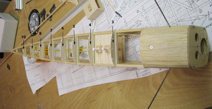
The configuration I chose to satisfy the above three requirements is shown
in the pictures below. After the tubes were bent to shape, balsa brackets
were glued to the fuselage structure, and the tubes inserted into the
brackets. After some adjustment and alignment of the tubes, they were CA'd
in place.
Left Side View
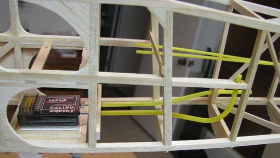
Left Side View from the Bottom.
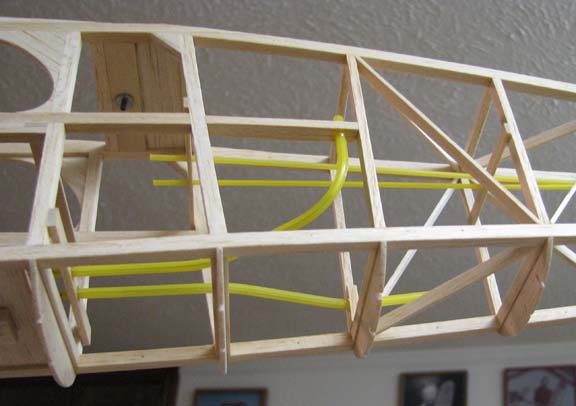
Another Left Side View.
This now completes both the electric power train and radio installations.
The next task for tomorrow is to glue the three stringers to the fuselage's
bottom bulkheads shown below and plank in around the two ABS tubes through
which the receiver is mounted.........................Tandy