.JPG)
Goldberg "Gas Bird" Construction Project Session #3
By Tommy Gray
AMA 17063
In the last session I did most of the work on the stab. Now I will build the rudders, and integrate them into the stab unit.
In the original Gas Bird, the rudder simply was glued to the top of the 1/4" longeron on the top of the fuselage, and filled in with some sheet balsa. On mine, I am going to do it in a little more substantial fashion, using a method I use on all my planes that have the rudder on top if the stab.
First, however, I wanted to add some sheeting to the center section of the stab in preparation for mounting of the stab. The sheeting will also make it easier to attach the unit to the fuselage, and give it a little more strength. As you can see in the picture below, I covered the top of the stab with some 1/16 soft balsa and tapered it into the front to add a little strength to the leading edge and to make it look a little neater. The leading edge is not very large and needs all the help it can get.
.JPG)
I also trimmed off some of the excess trailing edge in preparation for final shaping later.
.JPG)
I still have not cut out the elevators. This will come in a later session.
Now on to the rudders......
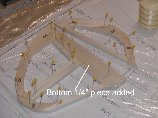
First, I framed up the outline of the rudders over the plans.
.JPG)
I did something different here I need to mention. On the plans, the bottom of the rudder was just a piece of 1/4" square balsa, which was supposed to have a "V" slot in the bottom of it for gluing to the top of the top longeron on the diamond shaped fuselage. I was not happy about this as my unit is for R/C and needs to have control surfaces, etc., cut out and I felt it had to be stronger. I do the same thing on most of my planes that I am doing on this one. Instead of the 1/4" square piece at the bottom, I added a piece of 1/4" sheet tall enough to go through the top of the stab all the way through to the bottom sheeting. This will make it not only stronger, but will make it a lot less easy to break off! You can see what I added below. There is one thing however that will be changed a little later but I will show you that in a few minutes.
Notice that there is a piece of 1/4" square at the bottom of the movable rudder. This will not stay, but will be replaced with a piece of 1/4" large enough to hold the control horn on the rudder itself. You can see it in the next picture.
You may have also noted the notches I cut out in the bottom of the rudder unit. These are to allow it to fit down into the stab itself. Now onto the fitting.
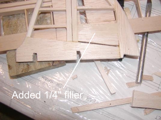
First I cut a 1/4" wide slit in the top sheeting of the stab, the same length as the rudder unit, less the part that is on top of the trailing edge.
.JPG)
This slot allows the rudder to fit down into it and go all the way to the bottom sheeting as previously mentioned. The notches allow it to fit down over the spars, and the trailing edge. Note also that I have not separated the rudder and fin yet. This I will do at a later time. In the next picture you can see the rudder fitting snugly into the slit on top of the stab unit as planned. The slit is tight enough that the rudder will stand up in it without glue. Once I am done, I will put in a little glue and permanently glue in the rudder unit, but that will probably come after covering.
When I planned the elevators, I designed in enough room in the center of the stab to allow sufficient rudder throw for good control of the plane. As you can see, there is plenty of room for good throw!
.JPG)
More to come later....Tommy!