Comet "Phantom Fury" Construction Project Session #2
Comet "Phantom
Fury" Rubber Powered
Free Flight Model Airplane
By Tommy Gray
AMA 17063
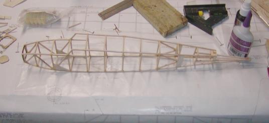
Well the fuselage is about framed up, minus a few tiny details.
During the build I have been going back
and forth between the Jim O'Reilly plans and the Comet kit plans to help myself
understand the way the thing is supposed to be built, as some things were just a
little unclear to me. Doing this cleared up most of the "difficulties" for me.
On Jim's plans I did not see any way to mount the sub rudder, nor did I see
anything to glue the windshield bottom to but the tissue covering on the
fuselage.
To me that was not acceptable, so I felt there had to be a better way. Voila!
The Comet plans show using 1/16 balsa sheet to fill in above and below the stab
thus solving my problem. I also noticed that there appears to be some balsa
sheet in the aforementioned area beneath the windshield, so there was my answer,
and as you can see, the sheet went in next.

Also there is the split piece of wood
in front of the rudder, which allows the dethermalizer to let the rudder/stab
assembly tilt up into the fuselage about 45 degrees, instead of having the rear
of the fuselage just fall off, like the Comet plans show. Much better idea in my
opinion (thanks to Jim O'!!). I will probably not use the DT, but will build it
in, anyway
Next, with the fuselage about 90% done I decided it was time to build the tail
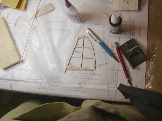
feathers. I started with the rudder.
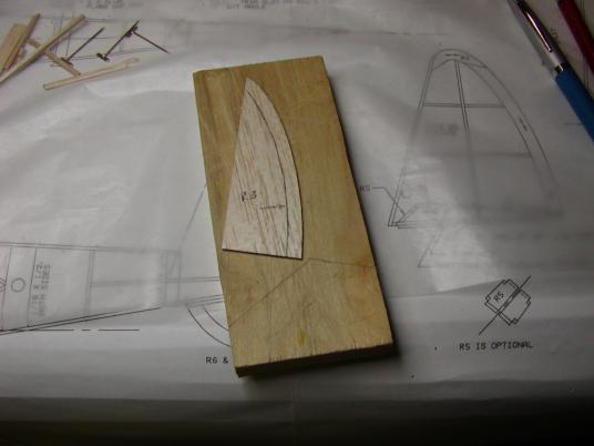
Uh Oh!! The Holman kit had a problem!! R3 that was supposed to be a part of the
outline structure of the rudder was a solid sheet that would have covered about
1/2 of the back of the rudder/fin assembly! No Good!!
.JPG)
R3 like the plans showed did not exist in the kit. This was a problem. Well not to be outdone, I pulled out the piece of 1/16 marked R3 on the laser cut sheet, and cut my own R3 and got back on the rudder build. I had to add a tiny piece to the top of it to make it fit as well. I could have used a solid piece, but all the 1/16 sheet I had in-house was a little too soft to suit me and the kit wood was plenty hard for the outline of the rear side of the rudder. The little kit discrepancy slowed me down, but I pressed on undaunted!! You can see what I did in the next few pictures.
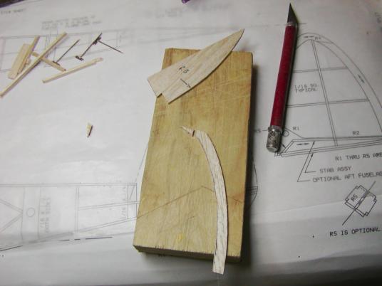
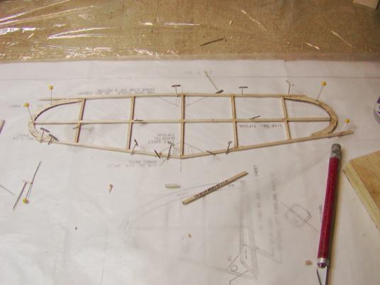
Well, a little trimming and sanding and we have a rudder!
.JPG)
With the rudder finished according to
the plans, I pressed on with the sub fin. Five minutes and a little CA glue later,
it was done as you see here.

A little trimming, and sanding, and we have a sub fin!
.JPG)
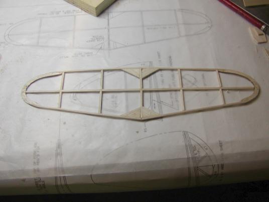
Next, the stabilizer was on the agenda. This one took slightly longer, as I had
to cut the diagonal braces, but it went fairly fast.
After the major framing was complete, I pulled it from the plan and trimmed it up. A little trimming here and there, and we have a stab!
I stopped at this point to do quite a bit of sanding to all the structure parts.
I use sanding blocks I make on the table saw out of scraps of the 3/4" Cabinet
grade birch plywood and using contact cement, I glue various grades of
sandpaper to each block until I have a nice set of sanding blocks. These last
quite a long time, (especially the ones with the coarser grits of sandpaper). If
you ever wear out a sheet of the sandpaper, just tear it off, clean up the block,
and glue on a new one. Then, you are good to go all over again.
Also, you may not have noticed, but if
you will look at the back sides of the sanding blocks, you will see the marks
from my X-acto (tm) razor knife, as they make great cutting boards!!


Well, the wife is calling. It is about time to eat, so this will have to wait until a better time!
Enjoy!
More to
come...........Tommy