Rocketeer A
Project
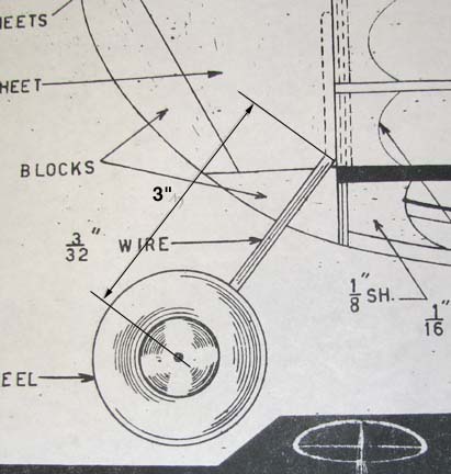
I checked out the plans carefully before I
started bending up the wire landing gear for the Rocketeer A. In the
plan's side view you can see that the exposed 3/32" wire landing gear leg
measures 3" as shown below. However, this distance is not the true
length of the leg because it is a projection from the side view and does
not account for the spread of the landing gear axles.
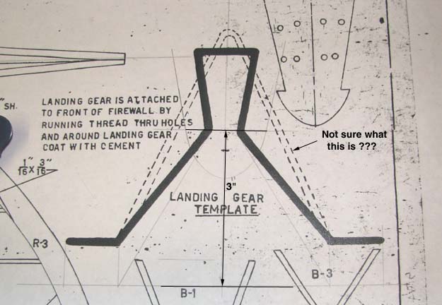
Sure enough, when I examined the front view of
the landing gear wire drawing on the plans shown below, it was in error in
two different ways. The size of the wire drawing
(the black one)
was entirely too large (1/8" or
3/16") and the landing gear legs were too short for
the projected 3" length. Then there is the dotted outline, which I have no
idea what it is for?
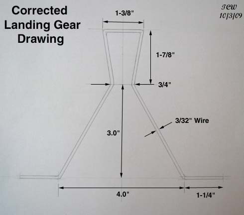
So this morning, I took the time and laid out a
correct flat view landing gear drawing with dimensions as shown below.
I always leave the landing gear axles long for interfacing with the
fuselage rack for transport.
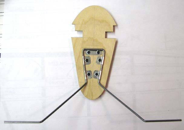
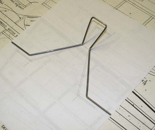
This is a pretty difficult shape to bend up out
of 3/32" piano wire as you can see below. Oh yes, at this point the axles
are even longer that the 1-1/4" shown on the drawing above, but I will
trim them off later with a Dremel cut off wheel.
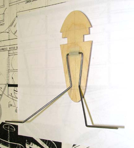
This picture shows a trial fit of the landing
gear on the firewall.
Next I bent up metal straps out of some K&S
.01" tin sheet stock to attach the landing gear to the firewall with. The
method I use to bend the straps is illustrated in the picture below. The
strap is squeezed around a 3/32" drill bit in a small vise.
Important: Notice the
aluminum angle behind the strap.
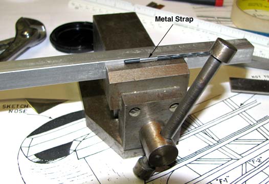
A 1/2" aluminum angle is used to keep the strap
flat on the backside when it is squeezed down as shown below.
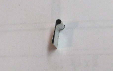
The top strap was made double width and uses
two 2-56 cap screws to attach the top of the landing gear wire to the
firewall. A single width straps was used on either side near the bottom as
shown below. Four 2-26 blind nuts will be installed on the back side of
the firewall to screw the cap screws into.
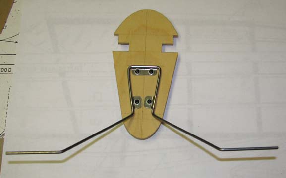
When I had finished, I noticed that the top of
the landing gear wire could slide back and forth a little in the double
strap on the top, so I added an additional single strap on either side
near the top as shown below. This configuration of metal straps locked the
landing gear wire down solid against the
firewall................................Tandy