Carl Goldberg's 1940 Comet Sailplane
HISTORY
(The events leading up to the selection)
I have wanted to build the Comet Sailplane ever
since I saw it the first time when I was a boy. This event is recorded in
the book I wrote about Ray Matthews' life and his free flight designs. The
excerpt from page 4 of my book records where I first saw the Comet
Sailplane:
"In the spring of 1947, when I was twelve years old, I
first met Eugene (Gene) Bonenberger in Oklahoma City. He and some of his
friends were teaching me to fly U-Control in McKinley Park near where we
lived on 10th Street. We rode our bikes to the Schmidt Model Shop
next to the Villa Theater out on 23rd Street. I became good
friends with the owner, Vivian Schmidt, and her husband Ralph. She nurtured
and encouraged me to become a model builder. Through her I met Ray Matthews
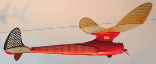
and his wife, Frances. Ray had a beautiful white silked Goldberg Comet
Sailplane with a green Orwick engine hanging from the ceiling in her shop
and I used to stand and admire it for hours."
The Sailplane has remained somewhere in back of
mind most of my modeling life. I purchased a copy of the original Comet
plans for the Sailplane in the late 1990's just to have them to look
at. Then sometime in the early 2000's Bob Holman laser cut the parts for the
Comet Sailplane plans and I bought the parts, again just to have them.
Building this model would require a long term commitment of time and focus.
And then there is the single wheel retractable landing gear, which has
always been a stumbling block for me.
TRIAL CONSTRUCTION
In November of 2004, I decided that I would build
the fuselage sides of the Sailplane just to see how Golderg's "ladder"
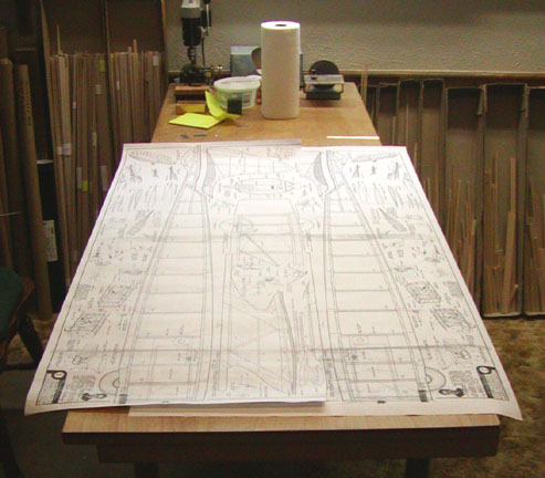
construction on the fuselage side frames would work out. In order to build
both sides, the first thing I did was to have a reverse copy made of the
fuselage profile plan as shown below.
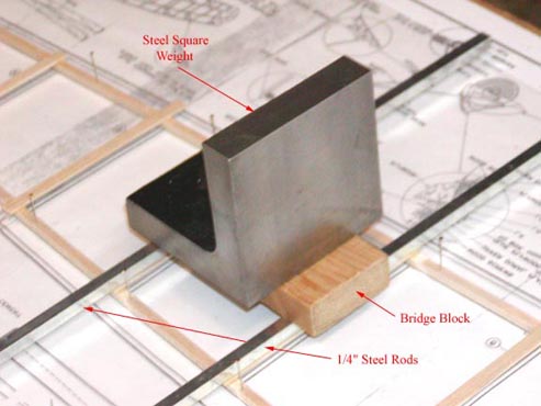
I had to devise a technique for holding the
1/16" X 1/4" cross members in place while the glue dried. The set up is
shown below. I bought some 1/4" square steel rods 12" long at the hardware
store and laid
them on top of two of the fuselage cross
pieces. I laid a short length of 3/4" x 2" pine bridge block across the two
rods and placed my 3" steel square cube on the block for weight. I let the
Titebond dry about 5 minutes, which was enough to hold the cross members in
place. Then I went to the next cross member and did the same thing all over
again until I was finished.
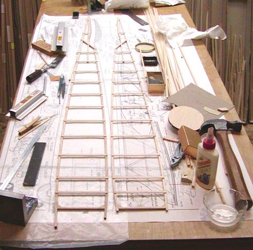
The resulting side lay up is shown below.
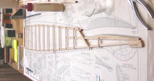
Then using the reverse copy of the fuselage
profile plan the other side was laid up as shown below.
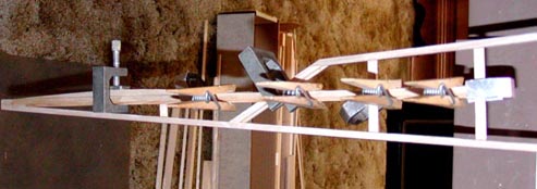
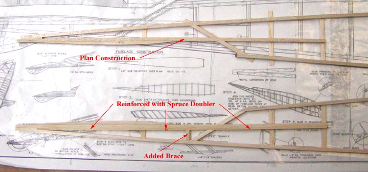
The aft end of the
structure appeared to be weak so I decided to reinforce the longeron
under the stab with a 3/32" X
3/16" spruce doubler. This shows the
spruce doubler on the top
longeron under the stab clamped in place while the glue dries.
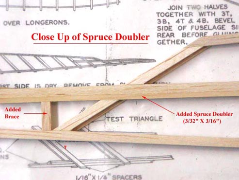
This shows a close up of the
spruce doubler glued in place. Notice that a portion of the diagonal truss
member had to be removed to allow the spruce doubler to fit down into
place. I also added the short 3/16" square brace between the spruce doubler
and the bottom longeron.
This compares the untrimmed
left fuselage side on top with plan construction to the trimmed right
fuselage side on the bottom with the added spruce doubler
and short brace between the
spruce doubler and the bottom longeron. Notice that the spruce doubler runs
the full length of the longeron under the stab.
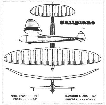
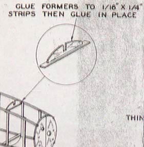
The Comet Sailplane plan does not show a top view
of the fuselage. :O< Instead, the top and bottom former pieces are first
glued to cross strips and then glued in place, which sets the width of the
fuselage sides as shown in this picture taken from the plan. Since it was
my intent to build the fuselage's primary frame and then stop the project, I
did not want to put on the former pieces with no stringers because they
would be subject to getting knocked off while in storage. So I joined the
sides by using the former pieces as spacers to position the width of the
sides and then gluing in the cross strips, which turns out to be a bit of a
trick if you think about what it takes to do this.
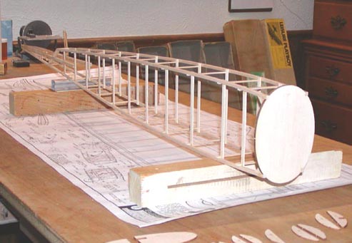
This right front quarter picture of the
fuselage's primary shows the two fuselage sides joined together with the
front balsa bulkhead glued in place. The structure turned out very straight
and very square. It is extremely light due to the thin 1/16" X 1/4" balsa
strips used for both the vertical and horizontal truss members. The frame
appears short and fat due to picture angle. Notice the former cross pieces
in the foreground that I used to set the frame width.
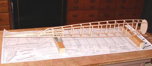
This picture is a better perspective of the
fuselage frame and shows it to be long and slender like a thoroughbred. You
can see that for its size, it is extremely light weight! At this point, I
discontinued the Sailplane project, which was my intent to begin with.
SAILPLANE PROJECT SELECTION
Recently, when Mike Myers announced in SAM Speaks
that he would be serving as the Contest Manager for the 2009 SAM
Champs, which he was going to call the Comet Model Champs, my interest in
the Sailplane was again aroused because "the model of the year" can be any
SAM legal Comet model.
Concerned over the complexity and functionality
of the retractable landing gear of the Sailplane, I seriously considered
selecting a scaled up version of the Class B Comet interceptor for my Comet
model because the retractable landing gear on the Sailplane was simply in
the "Too Hard Pile"! Then with some encouragement from Gene Wallock and
Sergio Montes, I started thinking about a more conventional two-wheel fixed
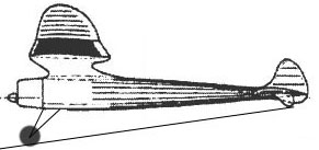
landing gear configuration for the Comet Sailplane and made the sketch below
of a possible two-wire strut landing gear, which surprisingly does not
detract too much from the Sailplane's beautiful lines.
At least for this afternoon, I have decided to
commit to an R/C Assist version of the Comet Sailplane for my winter's
building project. However, it is imperative that I locate another Series 20
McCoy 60 ignition engine for this project. Does anyone know one that might
be available for purchase.
I will be posting reports on the continued
construction as I go along..................................Tandy