Comet
Sailplane Project
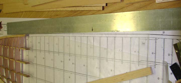
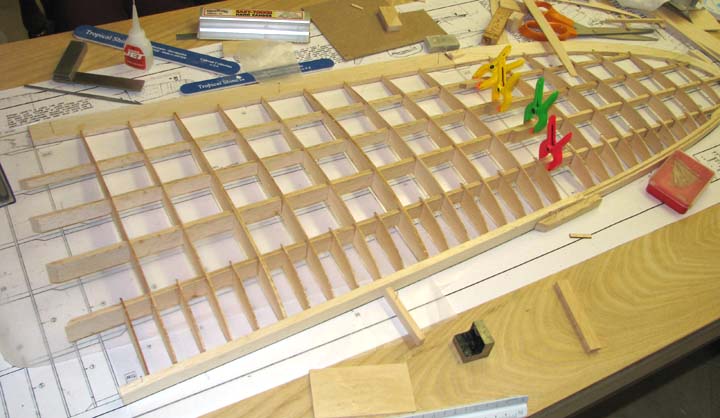
Saturday afternoon I started laying out the
wing's left inner panel. I cut the 5/16" X 3/4" leading edge from 5/16"
sheet stock and started to pin it down on the plan. It was then I noticed
that the wing's inner panel leading edge was actually curved
(I had initially thought it was straight). Against the
aluminum straight edge you can see the curve in the leading edge as shown
below.
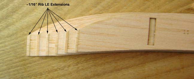
My next problem was that the rib's leading edge
of the ribs were short by ~ 1/16". I came to this conclusion by inserting
the four spars in an inboard and an outboard ribs and lining them up with
the tip panel's four spars. Since every rib was short, I glued an extension
on the leading edge of each rib as shown below and sanded each extension
independently so each rib would fit in its designated location.
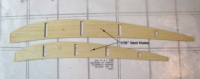
A 1/16" hole was drilled in each rib between the
center two spars as shown below to provide for venting between each rib bay
in the wing.
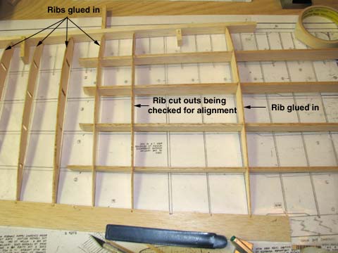
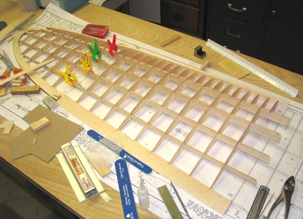
Custom fitting each rib to its location was
tedious exercise and requires some explanation. Not only did the 1/16" rib
extension have to be sanded to fit, but there was a constant sliding of the
four spars in and out of the rib cut outs to check and provide for
alignment. This was done in the following way. The inner most rib (near the
root of the panel) was aligned over the plans such that the spars were over
the spars drawn on the plans and it was glued in place (the rib on the right
below). Then the four spars were slid through this rib and down to the outer
most rib, which was also slid onto the spars. Then the ends of the four
spars were over lapped with the ends of the tip panel four spars and the
outer most rib was fitted and glued in place. The four spars were backed out
and the second from the outer most rib was slid onto the spars. The spars
were reinserted through the outer most rib and the second to the most rib
was sanded and fitted where necessary and glued in place. This process was
continued from the outer most rib moving inboard. The picture below shows
four ribs on the left glued in place and one rib on the right glued in
place. The fifth rib on left is being fitted and checked for alignment to
make sure the four spars will slide through the cut outs. If you don't go
through this process then you will be faced with trying to trim rib cut outs
with the ribs already glued in place which would be a disaster in my
opinion.
I also want to discuss the trailing edge I
used. The plans calls for a 5/16" X 1" trailing edge. I had to use a 5/16"
X 1-1/4" trailing edge to get the proper 5/16" thickness, but then I will
have to trim a 1/4" off of the trailing edge once the inner panel is
finished. Notice also that the LE of the trailing edge has been carefully
notched to receive the trailing edge ends of all of the ribs.
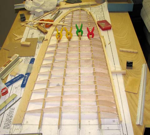
All four of the spars were inserted the final
time their overlapped ends with the tip panel spars were clamped as shown
below. Then the spars were glued to each rib on one side. Again 1/16" rib
extensions had to be added to all of the sub ribs and they were fitted and
glued in place as shown below in this leading edge view.
This is a trailing edge view of the inner panel.
This is an end view of the inner panel looking
outboard.
My next task will be remove the inner and tip
panels from the plan and bevel the ends of the leading and trailing edges
for the polyhedral joint. The plans show that the 14.4" span tip panel is
elevated 4-3/8", which forms a total polyhedral angle of 17.69 degrees. So
each side gets beveled 8.85 degrees. Oh yes, I will also have to trim 1/4"
off of the inner panel's trailing edge to make it 1"
wide...................Tandy