Comet
Sailplane Project
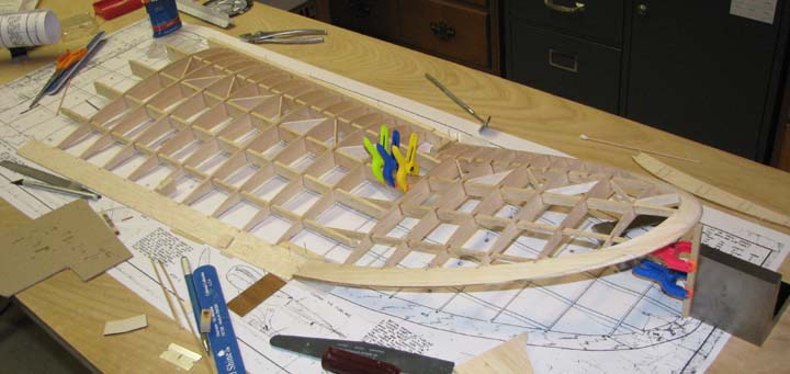
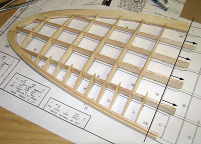
As shown below, the ends of the four spars extend
out beyond a line through the ends of the leading and trailing edges where
the polyhedral break takes place. This presents a challenges on how to bevel
the slopes on the ends of the leading and trailing edges because you can not
just block up the tip of the tip panel to the desired height and sand the
bevel in.
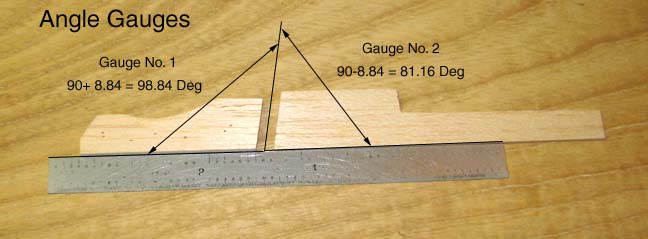
The total polyhedral angle is 17.687 degrees. The
leading and trailing edges of both the inner and tip panels are beveled at
17.687/2 or 8.844 degrees. To assist in setting up and measuring the slope
of the bevel, the two angle gauges shown below were made.
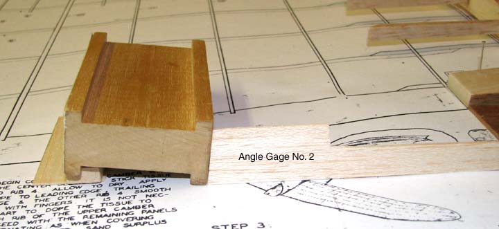
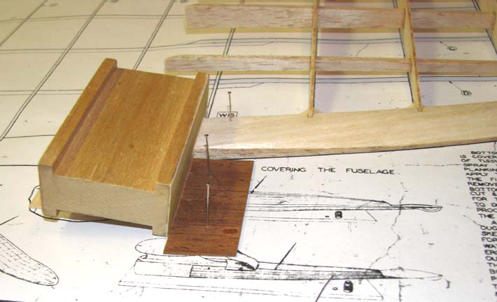
The slide of my bar sander was blocked to fit the
slope of Angle Gauge No. 2 as shown below.
A piece of 1/16" plywood was pinned down as a
sanding fence behind the trailing edge as shown below. The outside edge of
the plywood was also beveled. The slide of the blocked up bar sander is
gasped with both hands and carefully move it back and forth against the
trailing edge and sanding fence until the desired trailing edge slope has
been produced as shown below.
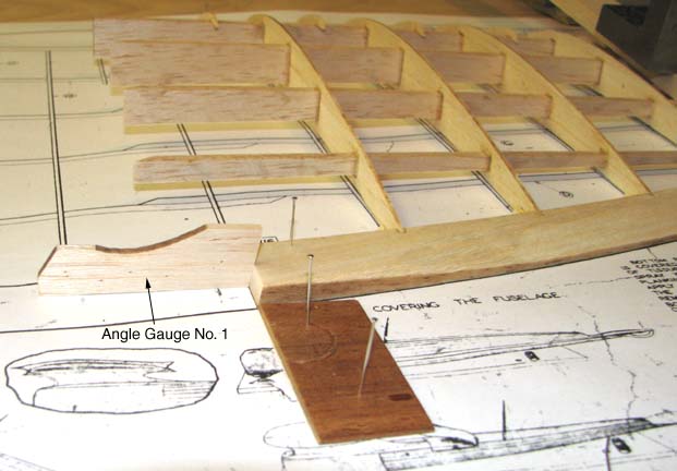
The beveled slope of the trailing edge was then
checked with the Angle Gauge No. 1 as shown below.
The same procedure was used to bevel the slope on
the end of the leading edge as shown below.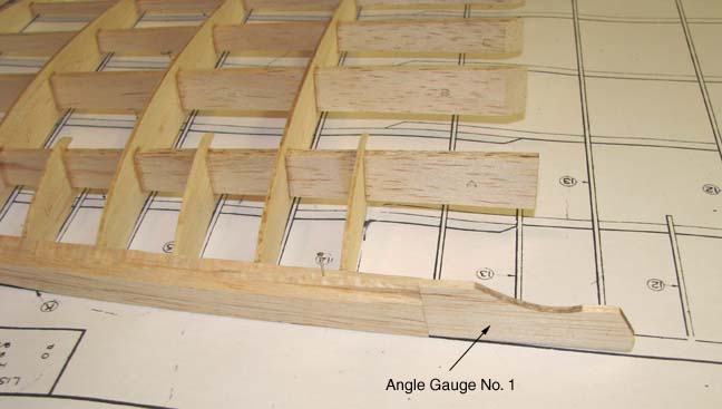
This procedure was also used to bevel the leading
and trailing edges of the inner panel. Then the wing's right tip panel was
jigged up to the inner panel with a rise of 4-3/8" and the leading and
trailing edge joints were glued first with Elmer Carpenter's aliphatic glue
and let dry. More Elmer Carpenter's aliphatic glue was then worked down in
between the second from the front spar overlap and clamped to let dry as
shown below. Then the right wing half was removed from the work table the
three remaining spar overlaps were glued and clamped in the same
manner.....................Tandy