Comet Sailplane
Project
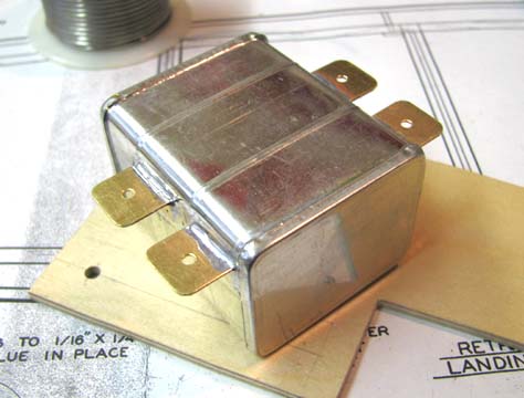
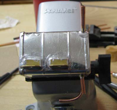
In Report No. 4 back on November 16, 2008, I
showed you this picture of the Sailplane's fuel tank with the
original tubing removed and sealed and the four brass mounting flanges
soldered to the sides.
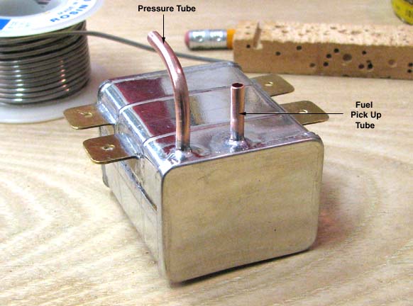
Yesterday I started work on replumbing the tank.
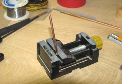
A piece 1/8" copper tubing was heated with a propane torch and bent into a
90 degree angle to form the pressure tube as shown below. A hole was drilled
in the top of the tank and the end of the pressure tube was inserted into
the hole and soldered in place. It only extends down inside about a 1/16" to
keep the engine's crankcase pressure from blowing bubbles in the fuel. The
fuel pick up tube on the other hand extends down all the way to bottom of
the tank in the center. The bottom end of the fuel pick up tube is filed off
on a 45 degree bevel to insure unrestricted fuel draw.
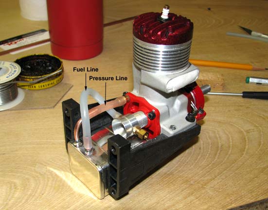
In this picture you can see the fuel line and the
pressure line connected between the engine and the tank.
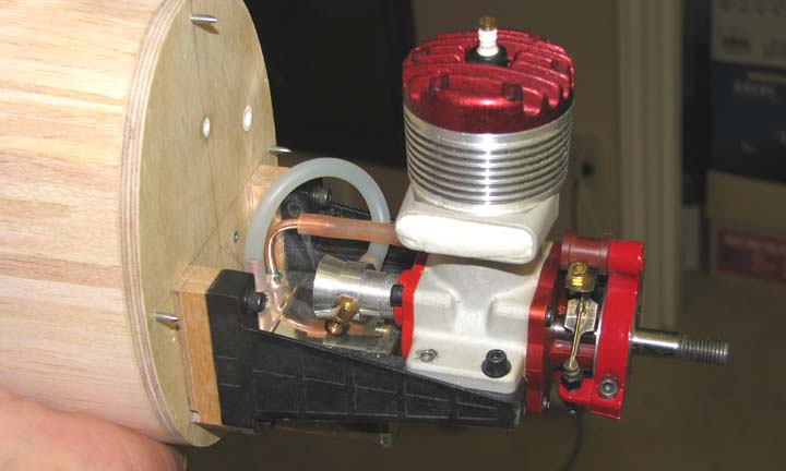
This is another view of the fuel and pressure
lines with the engine mounted to the fuselage.
This morning I continued with the plumbing of the
tank. First I cut a piece 1/8" copper tubing to length, put a slight bend in
the lower part of the tube and filed off the top end on a 45 degree bevel as
shown below.
As shown below, a hole was drilled in right lower
corner of the tank and the overflow tube was inserted into the hole and
soldered in place. The overflow tube runs diagonally up and over to the
upper left corner in the rear for the fuel overflow exit inside the tank.
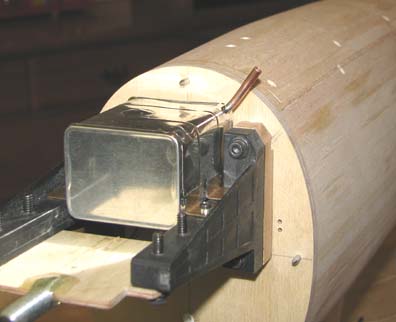
To check the angle the overflow tube makes coming
out of the tank, it was installed on the fuselage as shown below. The
requirement is for the tube to extend out perpendicular to the radius of the
fuselage as can be seen below.
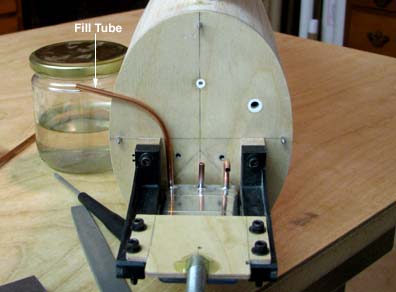
I cut another a piece 1/8" copper tubing
to length and put about a 60 degree bend in it by hand (no heat this time)
to make the fuel fill tube. A hole was drilled in upper right rear corner of
the tank and the fill tube was inserted into the hole only about a 1/16" and
was just tack soldered on one side as shown in the rear view of the tank
below.
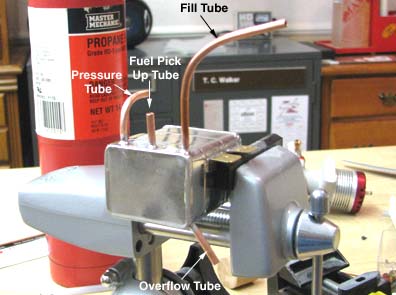
In order to get the location and angle of the
fill tube oriented properly, the tank had to be mounted back on the fuselage
again as shown below. Since the fill tube was only tack soldered in place,
it was relative easy to rotate and adjust the tube so that (1) the upper
part of the tube was flat against the firewall and (2) the tube extended out
perpendicular to side of the fuselage as can be seen below.
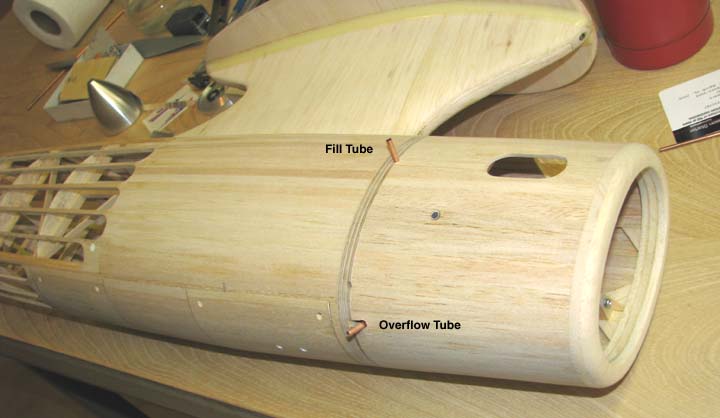
With some very careful marking, slot sawing of
the cowl's 3/32" plywood aft bulkhead, and some sanding with a 1/8" chain
saw circular file, two cut outs in the rear of the cowl were made for each
of the two tubes. As you can see in the picture below, the cowl fits flush
against the firewall and each of the fill tube and the overflow tube extends
out 1/2" beyond the cowl.
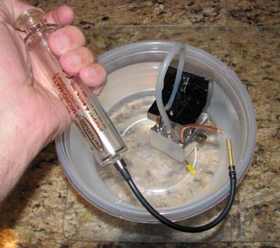
At this point, the cowl was removed and the tank
taken out of its mount. The pressure tube was hooked up to the fuel tube
with fuel line and overflow tube plugged, leaving only the fill tube open. A
glass syringe was attached to the fill tube and the tank was weighted down
in a bowl of water. Then glass syringe was plunged, pressurizing the tank as
shown below. There were no air bubbles escaping so were are no leaks in the
tank.
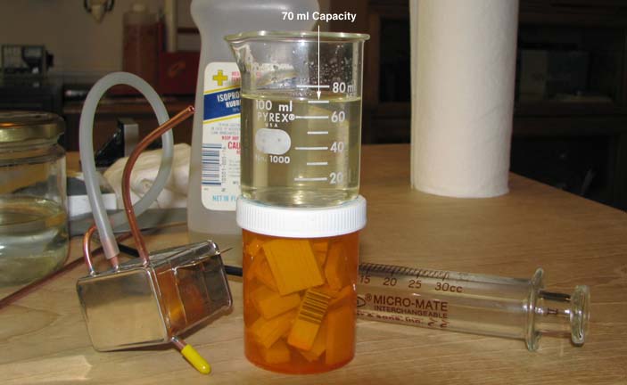
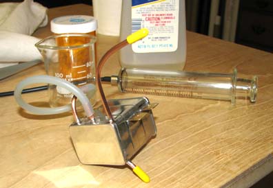
The tank was removed from the water and filled
with alcohol to overflow. Then the alcohol was carefully drained into a
Pyrex beaker. The tank holds 70 ml of alcohol as shown below, which is a
fuel capacity of 2.37 ounces. It had been a 2-1/2 ounce Perfect tank, but
the 1/8" tubes that I added inside reduced the capacity slightly to 2.37
ounces.
The tank was again filled with alcohol to
overflow and all tubes capped off. The alcohol will remain in the filled
tank for several days with periodic shaking. This will dissolve most of the
soldering flux and other contaminates that may have gotten inside the tank.
Latter on, the contaminated alcohol will be drained out and the tank flushed
out with fresh alcohol several times until the interior of the tank is
clean.
This completes the effort required to plumb the
fuel tank. Please realize that I know most of you guys know all of this
stuff just like I do. However, since I am documenting this construction, I
wanted to include the part about the tank as well tank as
well..................Tandy