Sailplane Construction Project Session #26
The vision in my right eye after cataract surgery
has recovered to the point where I can start working on the Sailplane again.
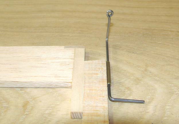
The design of the control horn for movement of the
rudder is one that I came up with for my Class B Playboy back in 1994 and that
was also used on the Playboy Junior that I complete this past August. It
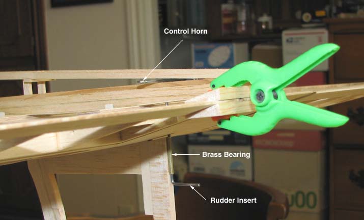
consists of a piece of 1/16" piano wire for the tiller and a short length of
brass tubing for the tiller bearing as shown below. The difficult part of the
design is forming one end of the 1/16" piano wire into a small eyelet as shown
below. This is done with the aid of a propane torch to heat and form the
eyelet using a multiple step process.
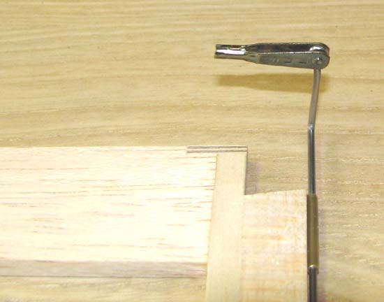
The wire is formed into a eyelet with a .063"
center hole to receive the pin on Sullivan clevis as shown below. Once
completed, the brass bearing is CA'd to the trailing edge of the fin also
shown below.
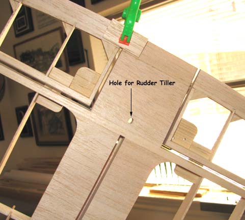
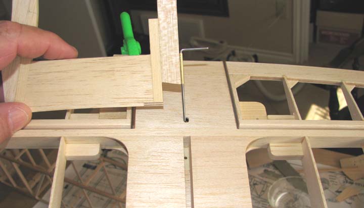
A small elongated hole for the rudder tiller to go
through is made in the top and bottom planking of the fixed portion of the
elevator as shown below.
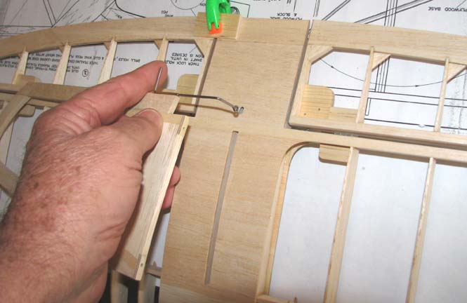
The assembly of the fin with the stab begins by
inserting the eyelet of the control horn through the elongated hole in the
stab as shown below.
The fin has to be rotated 90 degrees to maneuver
the bottom of the tiller through planking of the fixed portion of the elevator
as shown below.
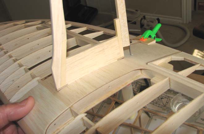
Once this has been accomplished, then the fin is
rotated back 90 degrees so it can be inserted in the slot in the top of the
stab as shown below.
The picture below shows the stab/fin assembled with
the control horn of the tiller protruding out the bottom.
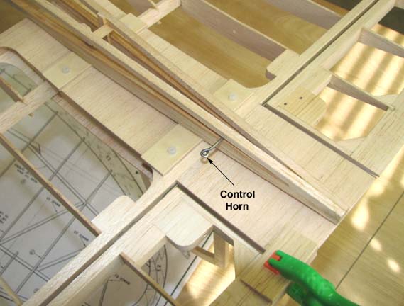
The control horn is now rotated 90 degrees to a
forward position and the entire stab/fin assembly is lowered down onto the
fuselage structure. The control horn is again rotated back 90 degrees so as to
extend out the right side of the fuselage's structure as shown below.
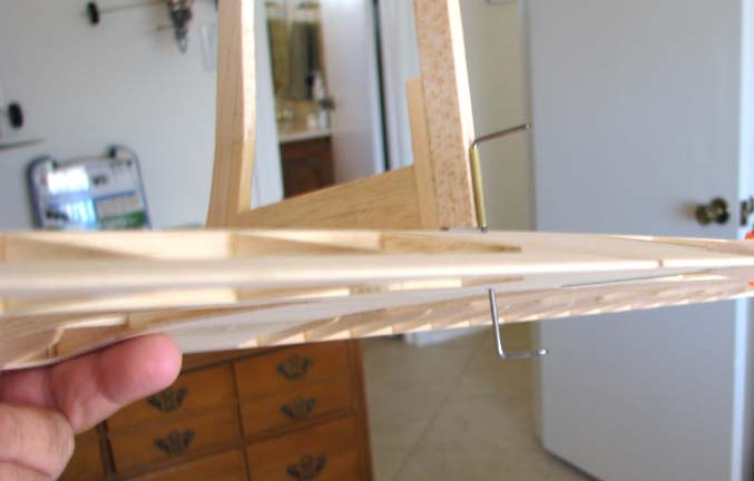
This inverted picture shows an edge view of the
rudder's tiller in place.
I realize this report contains a lot of extra
detail on such a small subject, but I wanted you to understand just what it
takes to implement a rubber tiller design like this.....................Tandy
Click Here to go to the
next page (27 )....