Futaba has three requirements to "maximize" the
2.4 gHz receiver's reception performance, They are as follows:
(1) The two antennae are to be 90 degrees to each other.
(2) The locations of the two antennae are to be as far apart as practical in
the model's fuselage.
(3) The two antennae are to lie in different planes.
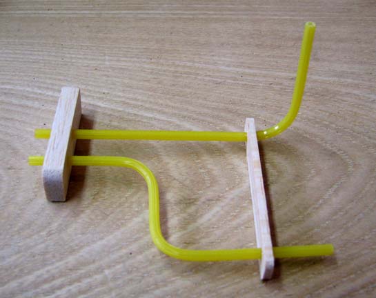
The configuration I chose to satisfy these three requirements is shown in
the picture below. I elected to use the standard Sullivan Gold-N-Rod, which
is yellow in color. It has a large enough hole in the center to accommodate
the FASST antenna diameter and can be bent to hold its shape. A piece of
1/4" balsa and a piece of 1/8" balsa are used to join the two antennae into
an assembly, which will be CA'd together later.
Here is a great tip if you
have not already discovered it.
Gently heat the Gold-N-Rod with a heat gun
and begin to bend it into the shape you want. Holding the shape you want and
while it is still warm, dip the bend in cold water and this will
instantly set the angle of the bend. If you miss the angle a little,
reheat the bend and it will start to release or unbend. Again, hold in the
angle you want and while it is still warm and dip it in cold water. This
will again setting the angle of the bend that you want.
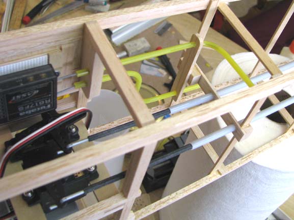
The picture below shows the antenna guide
assembly glued in place inside the Sailplane fuselage structure.
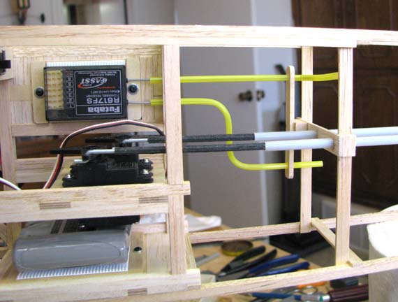
In the picture below, you can see that first the
piece of 1/4" balsa is glued into the frame work next to the receiver. Then
the 1/8" balsa spacer is adjusted out so as to fit against a 1/4" block
glued to the 1/16" X 1/4" cross member push rod guide. Once the spacer is
properly aligned, it is glued to the 1/4" block as shown below. Once the
spacer is dry, I will CA the Gold-N Rod tubes to both pieces of
balsa.............................Tandy