I started construction of the pylon on Thursday
evening, February the 12th and discovered a lack of information on how to
locate the pylon on the fuselage, which in turn lead to the fact that the
center of gravity was also undefined. So the past several days I have been
working trying to resolve these issue. Even though this is quite long and
drawn out, I think it is instructive to document what I have found out and
give credit to those who provided the critical assistance.
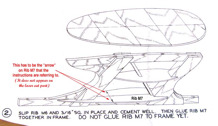
I laid up the 1/4" frame of the Sailplane
pylon Thursday evening as shown below. The doublers will be added to the
frame after it take up from the plan. Notice that the plan for the pylon is
intentionally shown away or removed from the fuselage structure so the
builder must follow the instructions on how and where to position it on the
fuselage. Note the pylon rib (M7) shown in phantom below, which is not to be
glued on the frame until the pylon has been attached to the fuselage
structure.

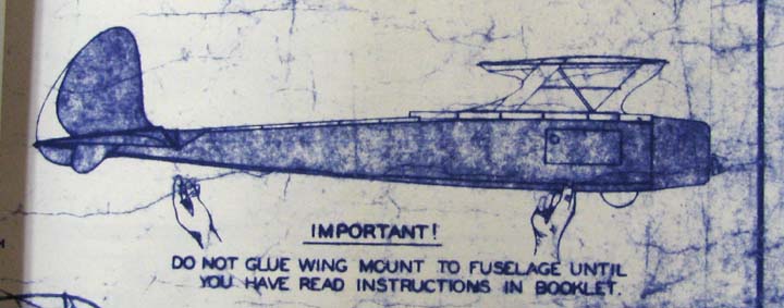
On the Sailplane plans, there is an instructional
note shown below telling the builder to read the instructions booklet before
gluing the pylon to the fuselage.
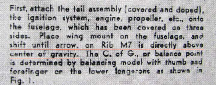
Some time ago, Gene Wollack sent me the .pdf file
containing the pages of the Sailplane booklet. In the instruction picture
below, it says to shift the pylon until the arrow on Rib M7 is directly
above the C.G. To begin with, Rib M7 isn't even glued on yet and there is no
arrow on Rib M7 or on the pylon plan anywhere?
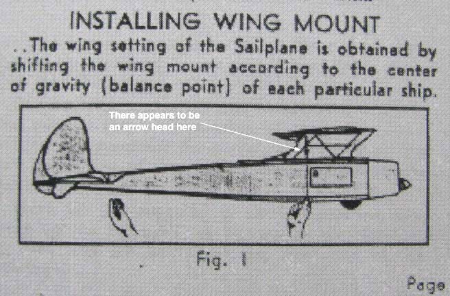
In the booklet's Fig. 1 shown below, there
appears to be an arrow head pointing down on the vertical line over the
right hand, but so what? I need to know where on the pylon frame to locate
the C.G. before I can located the pylon on the fuselage.
In discussions with Jim O'Reilly, he made the
following observation:
"I have a
copy of the original plans plus the instruction booklet, as you do. It
didn't make any sense to me either, until I noticed the isometric view
labeled No. 2, just above the back of the pylon in the side view. If you
look at ribs M7 in that isometric view, you will see a pair of arrows that
have no apparent purpose. I suspect that they were actually printed onto the
original print wood, and that this is your original reference point for
locating the CG relative to the wing."
To visualize what pair of arrows jim is talking about I scanned in the
isometric view labeled No. 2 for all to see below. Please note that
this represents the balance point without the wing and not the C.G.
for the complete model including the wing!
This
morning, Alfredo sent me this suggestion: The ideal solution should
be to take a look at a pristine Comet Model Airplane & Supply Sailplane
kit. If my memory do not fail, I recall that Gerald Martin had a virginal
kit with all the pieces in the original Comet box, so he could be the man
to be consulted about the exact arrows position printed on M7 split rib
...
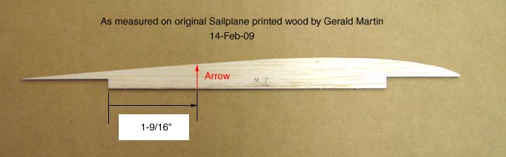
I contacted Gerald as follows: If you do in fact
have the Comet kit, please measure the position of the arrow on Rib M7
e-mail it to me. He measured the location of the arrow on the M7 printed
wood and sent me his measurement of 1-9/16" as shown below.
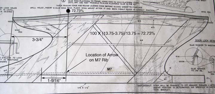
Transferring Gerald's measurement to the pylon
plan, you can then determine the distance from the pylon's trailing edge to
the Wing Off
C.G. as 3-3/4" as shown below. This places the
Wing Off C.G. at 72.73%
measured from the forward edge of the pylon.
The
Wing On or complete
model C.G. is one other important piece of information I got from Steve
Rozelle. Since he flies the Comet Sailplane, I contacted him to see where
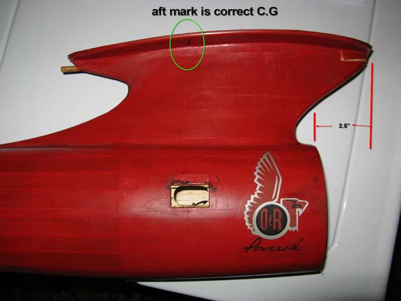
his model balanced. Steve responded as follows:
Tandy,
My balance mark is between 5 and 5.5 inches forward from the Sailplane's TE. See pic
Steve
My balance mark is between 5 and 5.5 inches forward from the Sailplane's TE. See pic
Steve
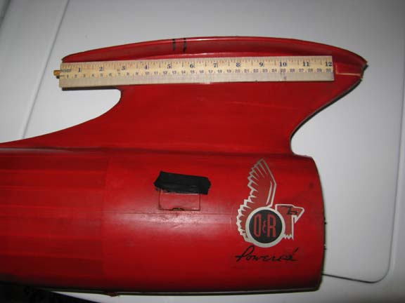
So Steve complete model, including the
wing, balances at 5-1/8". This 62.73% of the Sailplane's wing's 13-3/4"
root chord. In addition, Steve sent me a distance of 2.5" from his firewall
to the forward edge of the pylon as shown below.
To summarize the key results, I present the
following:
1. The arrow on the
original printed wood that is referred to in the Sailplane instruction
booklet is located 1-9/16" forward of the rear notch on the M7 rib.
2. To locate the pylon
structure relative to the fuselage structure, a point 3-3/4" from the aft
edge of the pylon is positioned over the model's
Wing Off balance point.
This is equivalent to a Wing Off
balance point of 72.73% of the wing's root chord.
3. There is an Edco powered
R/C assist Comet Sailplane flying with its balance point at 62.73% of the
wing's root chord.
............................................Tandy
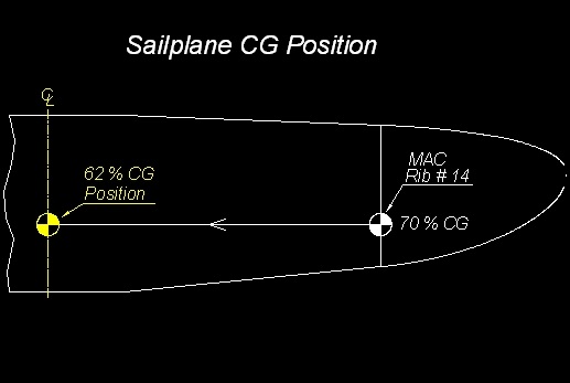
There is one other piece of information from Alfredo Herbon I forgot
to include in my Report No. 43. Alfredo took the figure below from
an article by M. Combs appeared in Model Airplane News, January 1959,
which shows the Sailplane CG at 70% measured at MAC ( Mean Aerodynamic
Chord ).

Alfredo indicates that for the Sailplane, the MAC is virtually
coincident with the wing chord at outward dihedral brake ( Rib # 14
). He projected the 70% CG position into the wing's center or pylon
position using AutoCad to arrive at a 62% CG on the central chord
position. Notice this agrees very well with Steve Rozelle's 62.73% CG
that I presented on the previous report. I am convinced that a 62% CG
is the right balance point for the Comet
Sailplane.................Tandy