Comet
Sailplane Project
(A Two-Part Report)
This two-part report is somewhat
long with a lot of detailed, but I feel that it is necessary to understand
my approach to the stab/rudder attachment to
the fuselage. I want to begin by reviewing some
Sailplane design features and recapping some of the construction I
have completed so far and then discuss the modified installation of the stab
platform and fuselage fairing.
*******************************************************************
Part 1
Background and Recapping
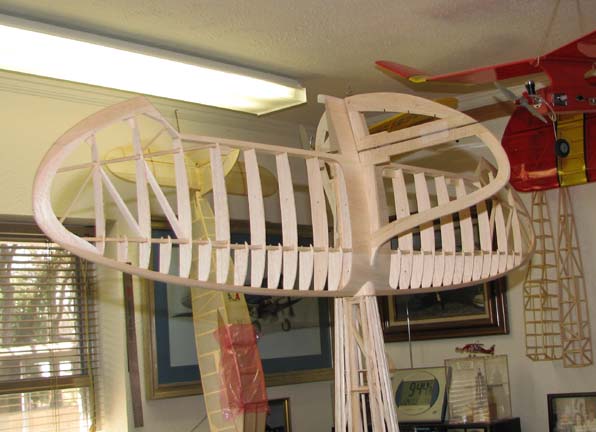
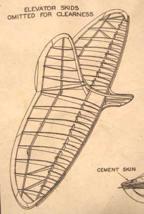
The Sailplane stab/rudder structural assembly is
shown in the sketch below taken from the Comet plan. As you can see, The
structure is built extremely light for free flight and incorporates a
fuselage fairing built onto the front of the assembly.
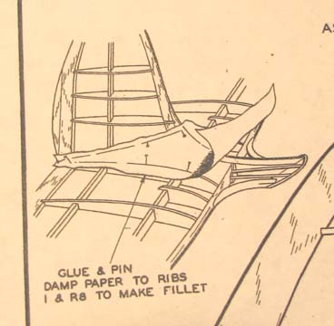
The kit designer shows a very large stab/rudder
fillet made out of paper, which is dampened and glued in place as
illustrated below. I simply could never accomplish this and besides, it
would be too fragile to last for any length of time.
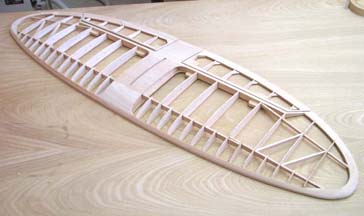
Tail structure modifications started when I built
the stab shown below. To provide for removal, attachment hard points were
designed into the center section and the center section was planked on top
and bottom. In addition the stab was modified to incorporate a center slot
for attaching the fin also shown below. No fuselage fairing was built onto
the front of the stab.
However, the aft end of the fuselage structure
was initially built according to plan with the structural incline shown
below. This is for interfacing with the design fuselage fairing built onto
the front of the stab, which I do not have.
A decision was made at this point to depart from
the plans on how the stab/rudder structural assembly with its big paper
fillet would interface or fair into the fuselage. The fuselage's structural
incline was eliminated by squaring it off in front of the stab with 3/16"
square longeron strips as shown below.
Then an aft bulkhead was made and glued to the
rear face of the squared off aft fuselage structure as shown below.
*******************************************************************
Part 2
Stab Platform and Fuselage Fairing
I have spent the last few of days working through
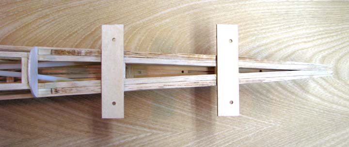
the design and details of installing the stab platform on the fuselage. The
stab platform 1/8" balsa sheeting will fill in forward, between, and aft of
the two 1/8" plywood stab mounts shown below.
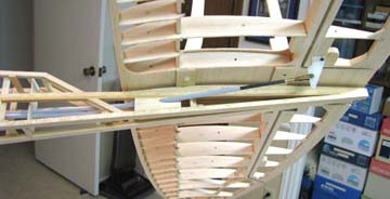
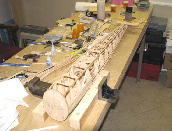
The picture below shows the fuselage jig set up
used while the glue is drying on the segments of the stab platform 1/8"
balsa sheeting.
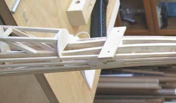
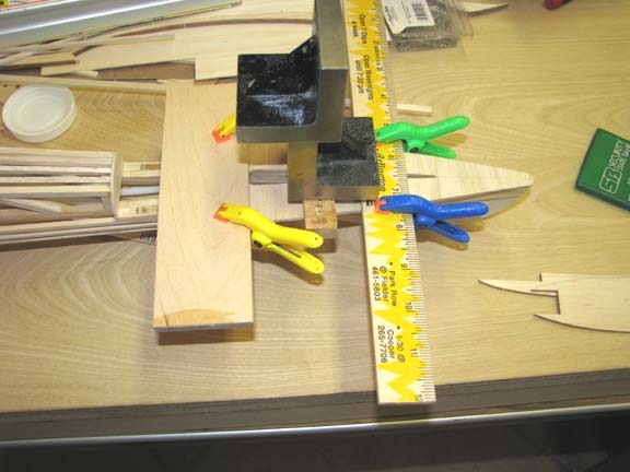
This picture shows a close up of both the
clamping and weighting used on the center segment of the stab platform 1/8"
balsa sheeting between the two 1/8" plywood stab mounts.
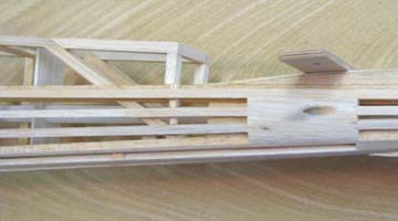
In the picture below, you see all three segments
of the stab platform 1/8" balsa sheeting glued in place from a top view.
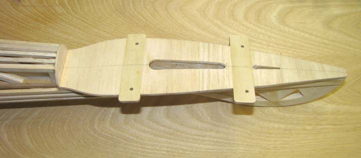
This shows the stab platform from a bottom view.
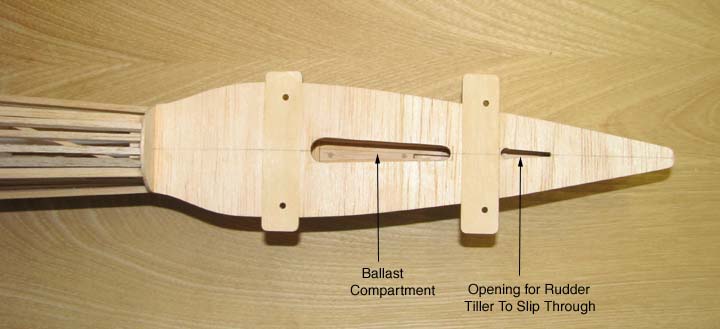
There are two openings in the stab platform shown
below. The forward opening is a compartment for ballast weight in case the
model is nose heavy. The aft opening is required for inserting the rudder
tiller when assembling the stab and fin/rudder to the fuselage.
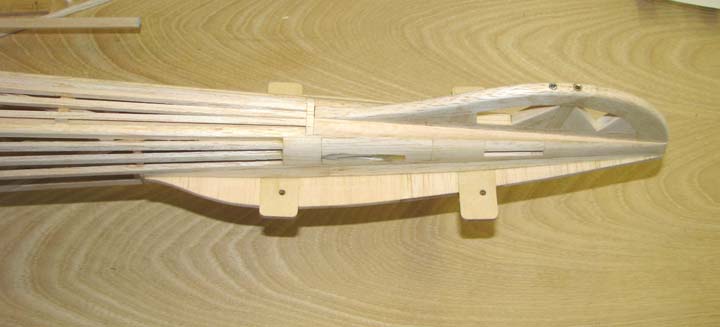
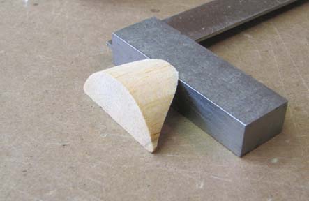
I spent considerable time carving, sanding, and
shaping the complex balsa fairing from the fuselage to the stab. A view of
the fairing from the top is shown below.
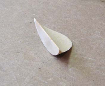
This is another shot of the balsa fairing from
the bottom showing the concave surface that interfaces with the top of the
stab planking.
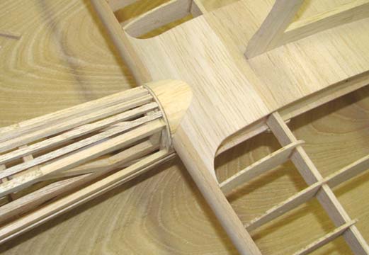
This picture shows a trial fitting of the balsa
fairing in place between the back of the fuselage and the stab. The fairing
still has to have some final sanding done to it before it fits in properly.
Also I have not decided just how to attach the fairing permanently, but
maybe it can be glued to the stab after the stab and fairing have been
covered.
In an attempt to flow the fin's leading edge line
down onto the stab and give the perception of a continuous fairing forward,
a small fillet was added to the fin's leading edge as shown below. The fin
and rudder will gain thickness when the symmetrical airfoil shaped ribs and
spars are added.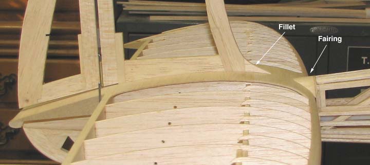
There are probably other approaches to dealing
with the Sailplane's complex stab/rudder structural assembly fairing issue
that would lead to a more authentic replication of the design on the
plan. However, while my modification approach does not replicate the large
stab/rudder paper fillet and fuselage fairing shown on the plan, it is
survivable, functional, and it is still within the
"Character of the Model"
as shown below..........................Tandy