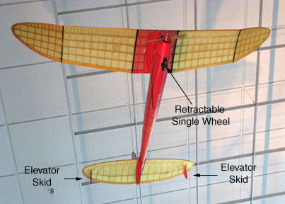
The Comet Sailplane was designed with a single
wheel landing gear that retracted up into the fuselage after take off. Two
elevator skids were incorporated into the bottom of the stab to stabilize
the model before take off while it was setting on the ground on the single
wheel. These two skids can be seen in the picture below of the Sailplane
model hanging in the lobby of the AMA headquarters' building in Muncie,
Indiana.
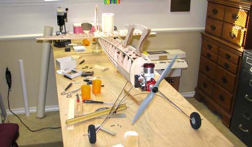
I am building the Sailplane for SAM R/C assist
and have incorporated a two wheel fixed landing gear as shown below.
Therefore, the elevator skids are no longer required. However, they are
definitely part of the
"Character of the Model" and
to leave them off would be a significant distraction in the
overall appearance of the Sailplane. So I decided to put elevator skids on
my Sailplane model.
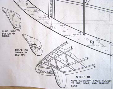
The elevator skids were designed to be attached to the stab by gluing them
to the rib, spar, and trailing edge of the stab as shown in the Comet plan
sketch below. This approach will not work for me because I want them to be
removable.
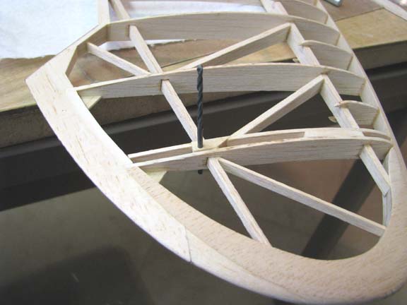
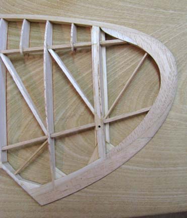
I started by adding an extra stab tip rib inside the existing one and spaced
over so the elevator skid would slide in between the two ribs. A piece of
bass wood was drilled out with a No. 44 bit for a 2-56 cap screw, cut to
shape, and glued onto the stab over the rear spar as shown below
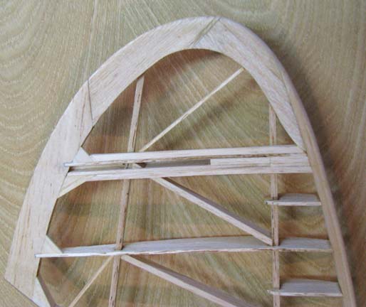
The elevator skid was inserted between the two
ribs and cap screw location was marked. A piece of 1/8" plywood was then
drilled and tapped for a 2-56 cap screw and glued in place at the proper
location as shown below.
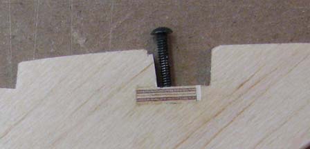
This is a close up showing the plywood insert.
Notice that the hole in the plywood insert was drilled and tapped at a
slight angle tilted aft.
1/8" balsa was filled in the space between the
two ribs, but just at the top, extending down only about 3/32" as shown
below. This serves a vertical "stop" when the elevator skid is inserted from
the bottom.
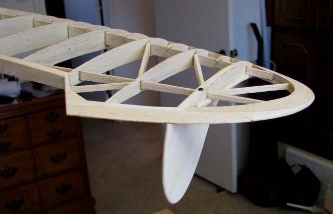
1/8" balsa strips were glued on either side of
the two ribs at the bottom as shown below. This not only adds additional
strength to the elevator skid slot, but provides or a 3/16" wide foot print
on either side of the slot for the covering to stick to.
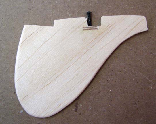
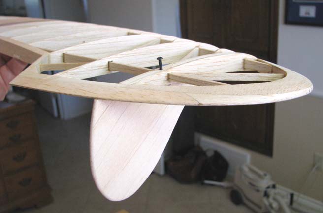
This picture shows how the single 2-56 cap
screw is inserted through hole in the bass wood on the top of the stab with
the elevator skid inserted in the bottom slot. Care must be taken when
locating the plywood insert in the elevator skid to make sure it is aligned
fore and aft as well as angularly with the axis of the 2-56 cap screw.
When the cap screw is tightened up, it pulls the
plywood insert in the elevator skid up tightly against the bottom of spar
and the entire length of the top edge of the elevator skid up against the
balsa inserted at the top of the slot, thus rigidly securing the it to the
stab.
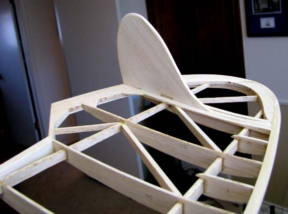
This picture shows the elevator skid/stab
interface from a bottom view of the stab.
So there you have it. An elevator skid design
that is both functional and removable. The removable feature allows
separation for ease of covering as well as flight testing without
the elevator skids until the model is trimmed. Later on, in the event of
severe skid side loading during landing, the elevator skid will actually
break off without damaging the stab structure itself because of the strength
of the slot. Then it is a simple matter of building a new elevator skid to
replace the old one. Now all I have to do is replicate this effort on the
left side of the stab! :O< ............................Tandy