After a fair amount of thought and planning, I
have begun construction on a jig fixture for building the McCoy 60's cowl
for the Sailplane. The approach actually involves making the rear cowl
bulkhead that fit flush up against the firewall as well a forward cowl
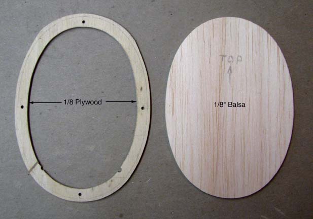
bulkhead that the cowl's outer nose ring will glue to. In the picture below,
the rear cowl bulkhead is a combination of an 1/8" plywood ring with four
3/32" alignment holes and an 1/8" balsa bulkhead overlay that the planking
will rest on. Notice the pencil line around the plywood ring on the left
that is set inside the outer edge by 3/32", the thickness of the outer
planking.
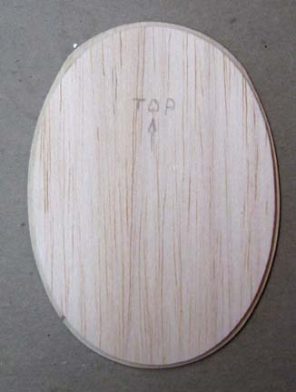
The 1/8" balsa bulkhead is overlaid and glued
onto the plywood ring coincident with pencil line around the outer edge as
shown below.
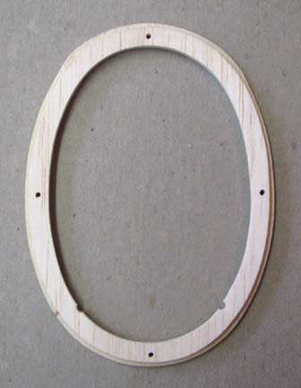
Then the interior of the 1/8" balsa bulkhead is
completely cut out and sanded flush with the inside of the plywood ring as
shown below. To compete the rear cowl bulkhead, the four 3/32" alignment
holes were drilled out as shown.
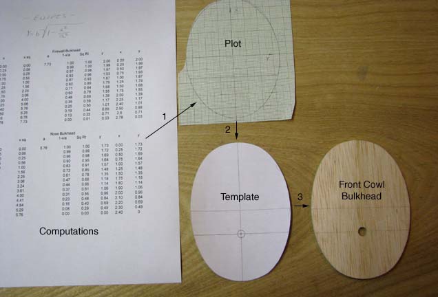
There was no forward cowl bulkhead drawing on the
plans. However, the height of the forward cowl bulkhead is shown on the
Comet plans to be 4.8". I drew in my thrust line to locate it on the
bulkhead's vertical axis. I calculated the ratio of the semi-minor axis to
semi-major axis of the rear cowl bulkhead (same as the firewall) to be
0.719. Using the 2.4" (4.8/2) as the semi-major axis of the forward cowl
bulkhead, I calculated the semi-minor axis to be 1.73" (0.719 X 2.4). Then
using the equation of an ellipse, I calculated the coordinates shown below
for the forward cowl bulkhead contour. These were used to graph the (1)
contour shown below. A template (2) was made, and then the actual forward
cowl bulkhead (3) was cut out of 3/16" balsa sheet. It will remain solid
until the cowl planking is complete and then its interior will also be cut
out.
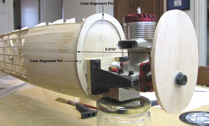
In order to determine the correct distance from
the front face of the rear cowl bulkhead to the back of the prop, the engine
was mounted on the firewall with the rear cowl bulkhead in place, the
forward cowl bulkhead was installed on the crankshaft, and the distance was
measured as 5-5/16" as shown below. You can also see two of the four the
3/32" piano wire cowl alignment pins.
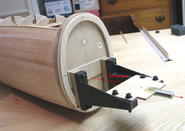
Now, accounting for the thickness of the cowl's
3/8" outer nose ring, allowing for at least an 1/8" prop clearance, and the
temporary 1/8" stand off behind the motor mounts, an adjustable jig
fixture was built up to achieve a 4-1/2" distance between the front face of
the rear cowl bulkhead to the back face of the front bulkhead as shown
below. The head of a bolt with the same diameter and threads as the McCoy 60
crankshaft was cut off and the threaded portion of the bolt was epoxied into
a 1/8" plywood plate. The center line of the bolt was aligned with the
bottom of the plywood to properly align the thrust axis. Four holes were
drilled in the 1/8" plywood plate to match the motor mount holes and the
plate was secured to the motor mounts as shown below.
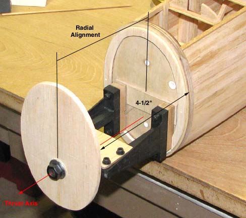
Finally, the forward cowl bulkhead was bolted to
the plywood fixture using washers and prop nuts on either side of the
bulkhead. The distance was then was adjusted to achieve the 4-1/2" dimension
and also radially aligned to rear cowl bulkhead as shown below. Before the
cowl is planked, cowl retention brackets will have to be designed and built
in place.
Building this jig fixture was as much work as
building the cowl itself, but it was the only way I could figure out to
build a cowl that would fit...................Tandy