Comet
Sailplane Project
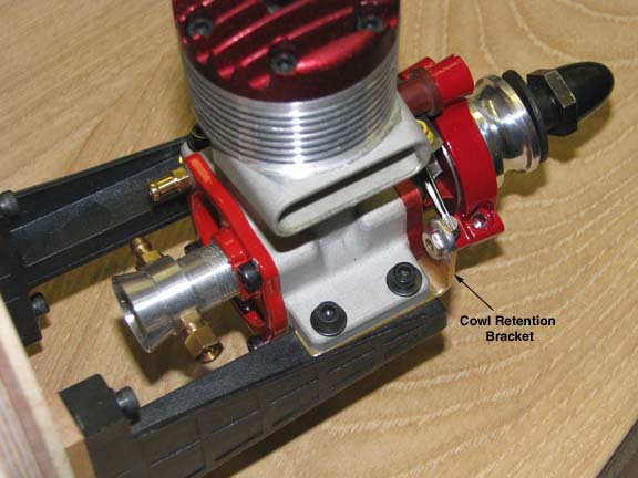
Once both cowl retention brackets were completed,
they were installed between the McCoy 60's mounting lugs and the composite
motor mounts for the trial fit shown below. This report will now discuss the
design and implementation of the two internal structural assemblies used to
retain the cowl on the fuselage.
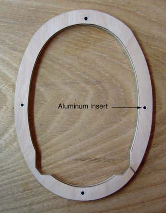
In the picture below you see the backside of
the rear cowl bulkhead. The cowl rear bulkhead has been notched out at the
bottom to clear the motor mounts and aluminum insets have been installed
in each of the four alignment holes to prevent hole wear from putting the
cowl on and taking it off.
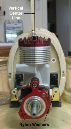
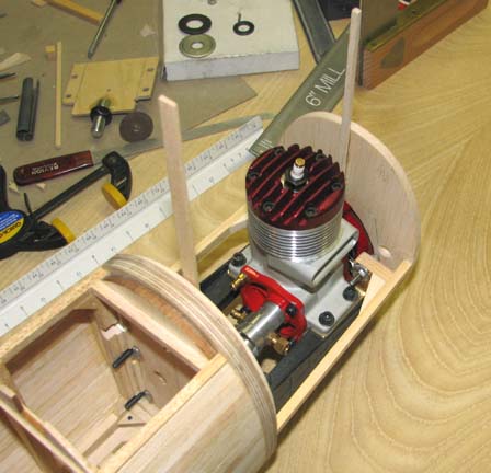
The picture below was taken from the front of the
engine to show several things:
(1) With the rear cowl bulkhead installed on
the four centering pins, a vertical balsa strip has been attached to the
firewall for the purpose of aligning the cowl front bulkhead.
(2) Two 3/16" X 1/4" notches have been made
in the in the 1/8" balsa rear bulkhead overlay for the cowl attachment
structure.
(3) A nylon washer has been CA'd to the front
face of each of the cowl's brass retention brackets for cushion.
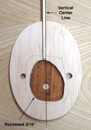
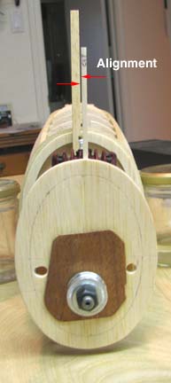
The backside of the front cowl bulkhead is
shown below along with its attached vertical balsa strip for the purpose
of alignment with the vertical strip on the firewall. Notice that the 3/16"
thick bulkhead has been cut out to clear the McCoy's timer assembly and a
piece of 1/16" plywood has been glued to the front face of the bulkhead. The
purpose is to mount this bulkhead on the crankshaft of the engine such that
the front face of the bulkhead is coplanar with the face of the engine's
timer assembly.
This picture shows how the alignment of the
cowl's front bulkhead with the firewall was accomplished. Notice that the
McCoy's prop spool was removed, the cowl's front bulkhead slipped onto the
crankshaft and over the timer assembly, then the prop spool, and a nut was
used tighten the prop spool against the front bulkhead. The cowl's front
bulkhead is now jigged in place and aligned to the cowl's rear bulkhead on
the fuselage's firewall.
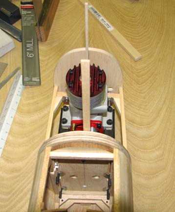
A hole for a 4-40 screw was drilled in a 1/4"
square spruce piece. This spruce piece was screwed to the cowl brass
retention bracket as shown below. A strip of 3/16" X 1/4" spruce was cut to
length to fit snugly between the front and rear bulkheads. The 1/4" square
spruce piece was then marked and cut to length so that the 3/16" X 1/4"
strip of spruce made contact with it when put in place. The two spruce
pieces were then glued together in place in the jig set up. The screw was
removed and a 1/4" balsa triangle was glued in to reinforce the structural
assembly. Finally the spruce assembly was glued to both the front and rear
cowl bulkheads as shown below.
This picture looking forward shows both the left
and right spruce assemblies glued in place.
From this point, I can now proceed to plank the
cowl. However, because of its length, I will stop this report and post it
for your review.............................Tandy