Speed 400
Cloudster Project
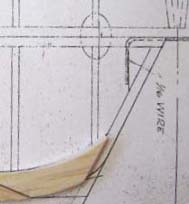
The plans call for a 1/16" wire to
connect the two halves of the elevator together as shown below.
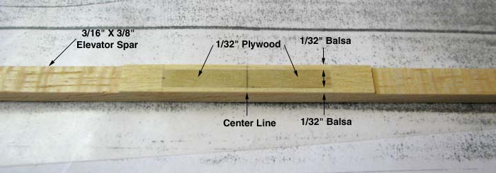
I decided to make a continuous elevator
spar to eliminate the 1/16" wire. To reinforce the spar at the center, a
1/32" plywood doubler was glued to the back side as shown below. Notice that
1/32" balsa strips 1/16" wide were added to either side of the plywood
double. This will make sanding a radius on the back side of the spar easier.
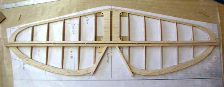
The lay up of the Cloudster's elevator
is shown below. Since small removable nylon hinges are going to be used,
notice the 1/16" gap between the stab spar and elevator spar to account for
the hinge. If you look at the spruce base for the elevator control horn, you
will notice only one 2-56 hole drilled and tapped. During the
installation of the elevator push rod, the alignment angle of the control
horn angle will be determined and then the second hole will be drilled and
tapped in the spruce base.
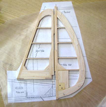
The lay up of the Cloudster's rudder is shown
below. Again notice that a 1/16" gap between the fin post and the rudder
post has been left to account for the hinge thickness. Also notice in the
picture the large balsa reinforcement insert in the lower part of the rudder
that fits around the spruce base for the control horn. If you look close,
you can see my sketch of the cut out for a carry through elevator
spar....................Tandy