Rocketeer A
Project
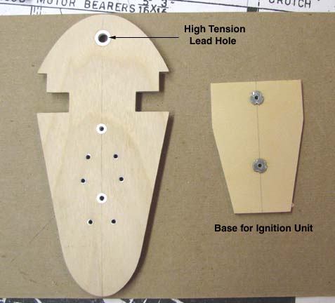
In the picture below, the firewall is shown on
the left and the base for the ignition unit on the right. The firewall was
predrilled for the high tension lead and the two 2-56 cap screws that hold
the ignition unit to the back of the firewall. White ABS plastic tubing
was inserted into each of three holes and CA'd in place. This liner will
prevent fuel and oil from soaking into the edges of the holes in the
plywood. Notice that there are two 2-56 blind nuts embedded into the
ignition base unit on the right.
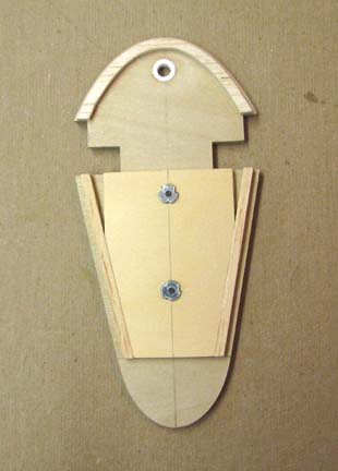
This picture shows the firewall from the front
with the 2-56 cap screws with washers threaded into the ignition unit base
attaching it to the back side of the firewall.
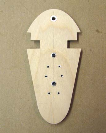
This picture shows the firewall from the back
side. Notice how the ignition unit base is keyed between "V" on the back
of the firewall, which automatically aligns the holes for the two
attachment cap screws. This completes the firewall. The next step will be
remove the ignition unit base and glue the firewall into the fuselage's
crutch frame......................Tandy