Rocketeer A
Project
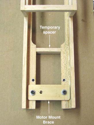
If you recall in Report No. 4, a temporary cross brace or spacer shown
below was installed just in front of where the firewall will be located
and I said (this one will be
removed later after the crutch is completed and the firewall has been
glued in place). To maintain the proper width of the
motor mounts in front, a plywood jig brace was made and bolted in the two
front motor mount holes as shown below.
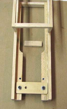
Then the temporary spacer was removed and the inside of motor mounts
smoothed up as shown below.
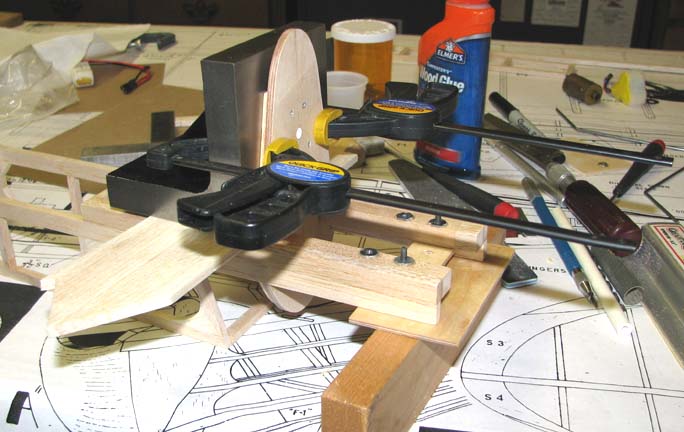
Aliphatic glue was applied to the edges of the firewall and motor mounts,
the firewall slipped into place on the motor mounts, and the excess glue
was removed with a Q-Tip and water. The firewall was squared with the
bottom of the motor mounts by placing a large steel construction block
square on the bottom of the motor mounts and then clamping the firewall to
the vertical face of the square as shown below.
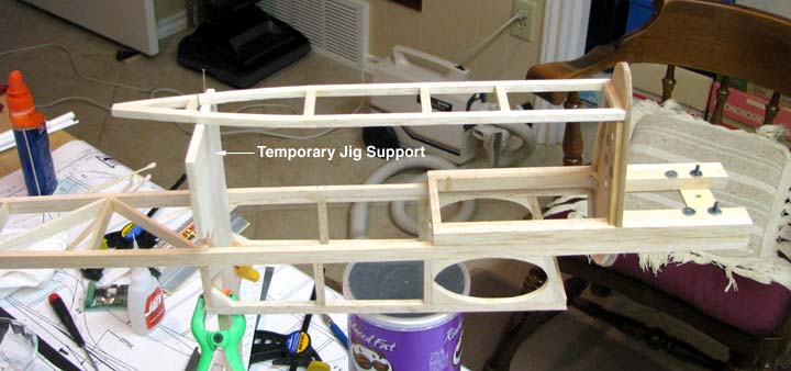
A temporary jig support was clamped in place to establish the correct
height and centering location of the rear of the bottom longeron assembly
as shown below. The front of the bottom longeron assembly was then glued
to the firewall and the rear pinned to the jig as shown below.
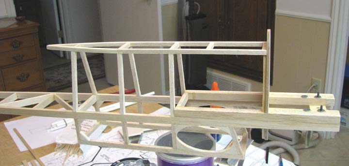
With the bottom longeron assembly firmly in place, three of the four 3/16"
sq. members that form the tapered fuselage sides were cut, fitted, and
glued in place on each side as shown below. Then the temporary jig support
was removed.
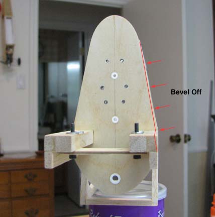
It was when I started to glue in the fourth side member that is directly
below the front of the cabin that I discovered I had made a major mistake
%$#@*& ! Looking at the picture below, you can see that the 1/4" X 3/8"
balsa strip laminated to the maple motor mount needs to be beveled off on
the bottom by 1/16" to line up with the rear side members. This in and of
itself is easy to do, however........................
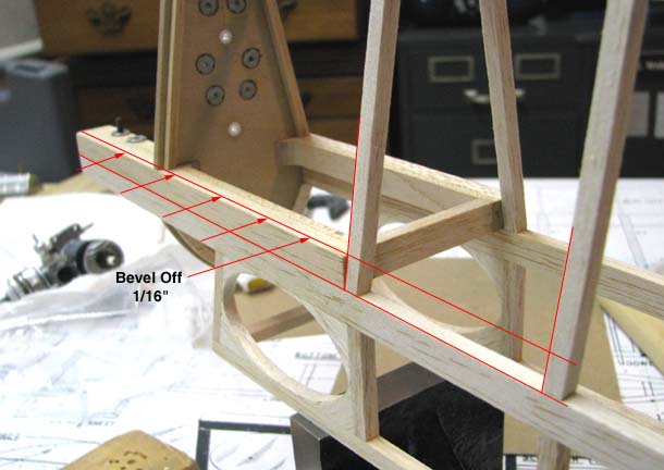
...............the 1/16" beveling will require the lower portion of the
1/8" plywood firewall to beveled off as well as shown below, which is
going to be a big deal! This causes other problems on the back side of
the firewall that I won't go into right now. This situation arose when I
laid out the firewall pattern. The sloping edge of the firewall should
have started at the bottom of the 3/16" X 3/8" crutch strip and not at the
bottom of the 1/4" X 3/8" laminated strip on the motor mount. :O<
Sooo, I now have to come up with an acceptable way to do this unexpected
beveling, which is a subject for my next report....................Tandy