Comet
Sailplane Project
I started laying out the wing's left tip panel
last Wednesday afternoon and finally finished the lay up this afternoon
because of a few problems I encountered. While the laser cut parts and wood
are outstanding, a few of the parts did not fit the plans. However, this is
not to say that most of the parts fit very well. The reason for the misfits
are because the Sailplane plans already existed so there was no CAD
file available for generating the laser parts cut file
(I think I am saying this right).
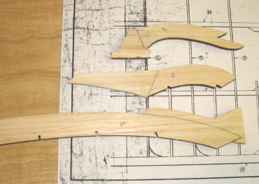
First of all, the w1, w2, and w3 tip parts all
needed a little modification to fit the wing tip contour. This was
accomplished by gluing on extra wood taken from the same sheet the part was
cut from as shown below.
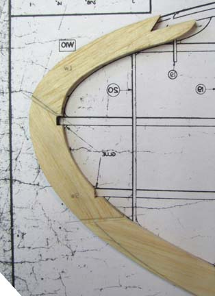
Then the extra wood on the parts was trimmed and
sanded to shape so that when the three parts were glued together they
fit the wing tip contour as shown below.
The four tapered 3/16" spars for the left wing
tip were removed from their sheet and lightly sanded to remove the laser
burn. Then they were trimmed and beveled on the ends and fit the plan
exactly as shown below.
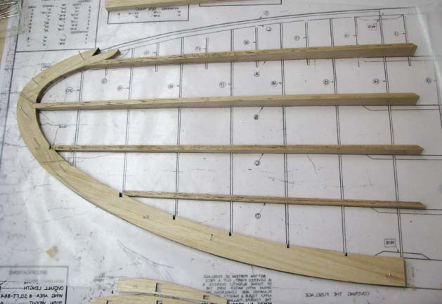
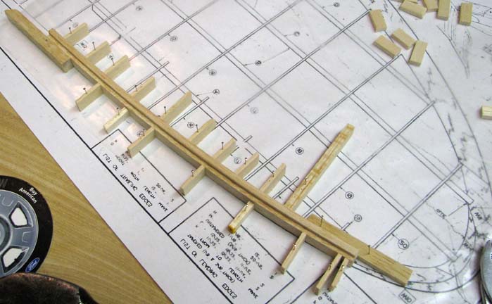
The 1/8" X 1/2" and 3/16" X 5/8" leading edge
pieces were cut a little over length and soaked in warm water. Aliphatic
glue was applied between the two damp leading edge pieces and the excess
glue wiped off. Then the leading edge pieces were bent to shape and pinned
down using a number of short blocks over the wax paper covered wing tip plan
as shown below. The leading edge is only slightly bowed, however the
combined 5/16" laminated leading edge requires some serious blocking up to
get it bent to shape. Once dry, the curve in the laminated leading edge will
permanent.
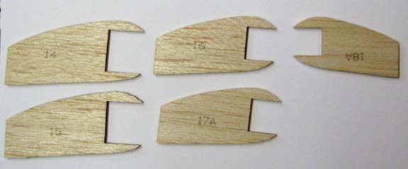
Then a problem with the sub ribs were found as
shown below. The No. 15 sub rib was a repeat of the No. 14, the 17A sub rib
was a repeat of No. 16, and the No. 18A sub rib was actually No. 17.
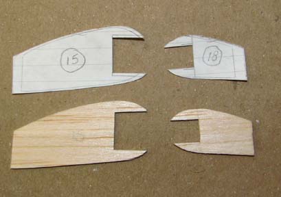
What this meant was that there was no No. 15 or
No. 18 sub ribs. In order to make a suitable pattern for each of these, the
forward shape of the full ribs on either side of the missing sub rib was
traced on a common piece of paper. The pattern was developed by drawing a
line between the two rib tracings and then the two missing sub ribs were cut
out as shown below.
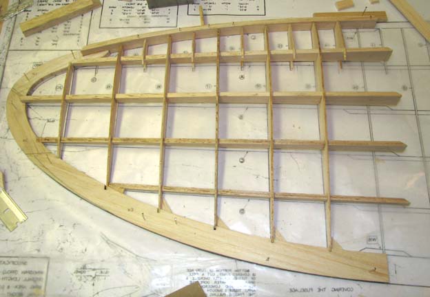
The bowed leading edge was trimmed to fit
the notch in the w1 tip piece and the assembled trailing edge, including the
tip, was glued to the leading edge. Then each of the six full rib was glued
in place between the leading and trailing edges, being sure that each rib
was perpendicular to the work table surface. Again, these laser cut ribs fit
extremely well, except the last tip rib, which was too short and not shaped
correctly.
There were several iterations of custom trimming
and tweaking of the rib cut outs required to get each of the four tapered
spars to slide straight through the cut outs in the all of the ribs.
However, with a little patience and persistence this was accomplished.
Finally five of the six sub ribs were glued in place as shown below. Oh yes,
3/32" gussets were added to the end of the ribs to help stabilize and hold
the wide trailing edge in place.
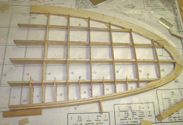
In the picture below you can see that soft filler
wood is going to have to be added to the top of the tip pieces where the
leading edge attaches to the tip. Notice also that the second spar from the
front is partially elevated relative to the tip pieces. So soft filler wood
will have to be added around the tip in order to get the wing tip sculptured
properly. Once this is completed, the last sub rib will be glued in place. I
think this structure is going to make a beautiful wing once I work through
all of the hidden challenges. :O)..........................Tandy