Comet Sailplane
Project
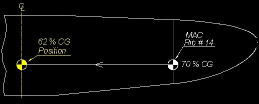
I out started yesterday morning by doing a center
of gravity (CG) evaluation on the Sailplane. The balance point came out at
8.8" aft of the wing's leading edge, which is (100 X 8.8/13.75) = 64%
CG. This compares with the design CG of 62% shown below
(see Ref. Report No. 43a).
I am not sure just how critical this 2%
difference is, but I simply can not take any chances during the first flight
tests with a possibility of a marginally stable airframe.
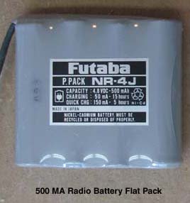
Without adding ballast weight, the radio's flight
battery shown below is the heaviest single item that I have to work with to
try and correct the CG.
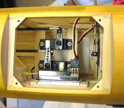
I removed the radio flight battery from under the
servos, but kept the battery mount in tact as shown below. It is possible
that after the initial flight test phase is over, I may want to put the
battery back in this location.
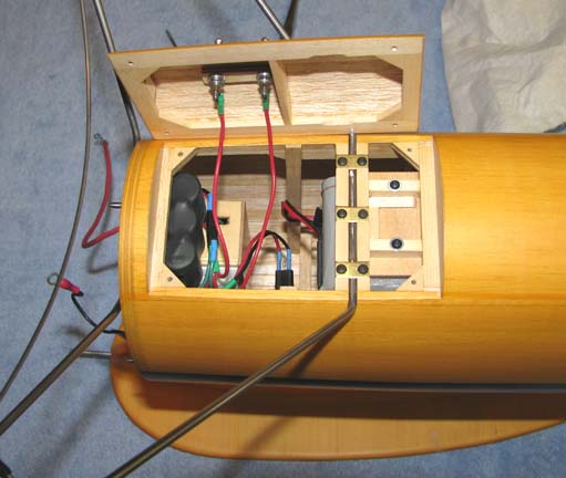
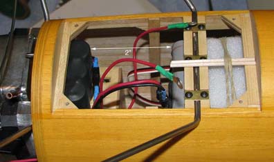
The battery was temporarily moved forward to
within 2" of the ignition unit as shown below. Hopefully this will not cause
any radio interference from the ignition system with new FASST 2.4 gHZ
radio.
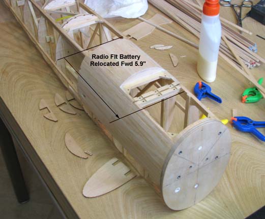
In the earlier construction picture below, you
can see that the radio flight battery was moved forward a total of 5.9".
I reassembled the model and rechecked the balance
point. It came out almost exactly on 8.5", which is the design CG of 62%.
The good thing about this location is that there is a lot of spruce
structure built into to fuselage in this area to support the rear landing
gear strut as shown below.
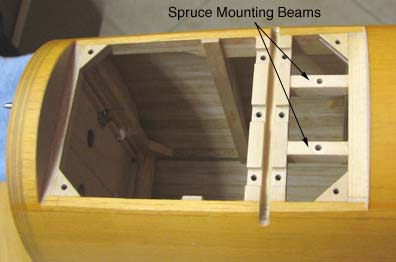
At this point I disassembled the Sailplane again.
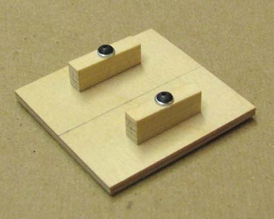
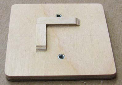
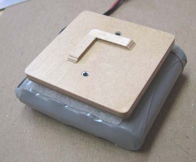
The new battery mounting plate was made from 1/8" plywood. Two small spruce
beams were cut to sized, drilled, and mounted to the plate using 2-56 blind
nuts on the top of the plate as shown below.
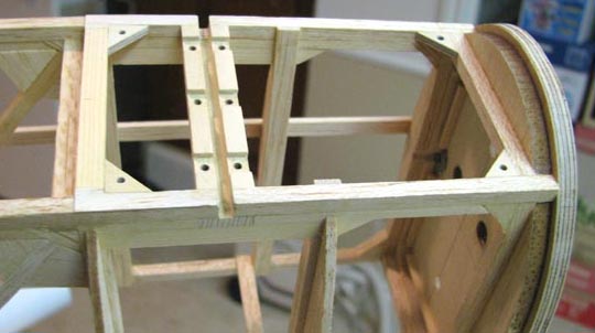
The two spruce beams were glued in place between
the landing gear rear strut spruce mount and the spruce member at the back
of the ignition hatch as shown below.
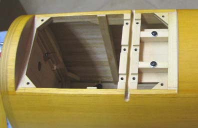
A trial fit of the battery mounting plate was
made with the two spruce beams as shown below. Notice that the battery's
plywood mounting plate is resting on the landing gear rear strut spruce
mount and the spruce member at the back of the ignition hatch, which will
resist any down "g" loads that occur during a hard landing and the two
spruce beams are not subject to this load. Their purpose is to hold the
battery on the floor of the fuselage and resist any axial g's.
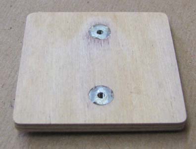
Two pieces of 1/32" plywood strips were located
and glued to the bottom of the plate as shown below. These strip
automatically aligns the blind nut holes to the mounting holes in the two
beams.
A piece of 1/32" plywood was cut and drilled to
fit over the backs of the blind nuts on the top of the plate as shown below.
This was glued on to the top of the plate to effectively countersink the
backs of the blind nuts and given three coats of clear nitrate dope to
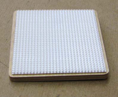
provide a smooth surface to attach the Velcro hook sheet to.
This shows the Velcro hook sheet installed on top
of the plate, which completes the new battery mount.
The radio flight battery was attached to the new
battery mount using the Velcro interface as shown below.
The battery plug on the radio's switch harness
was long enough to reach to the new location. The battery was plugged in and
the final installation in the fuselage is shown below.
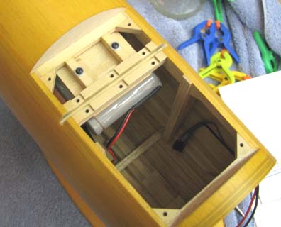
I took this final picture before I installed the
ignition hatch cover........................Tandy