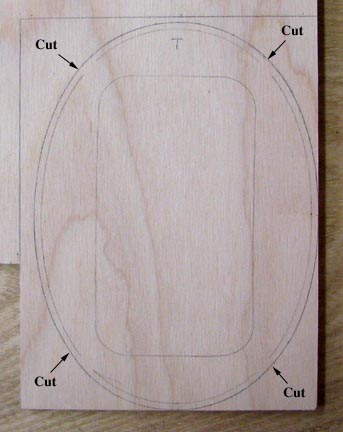
This shows the Sailplane's (SP) bulkhead No. 1
laid out on a piece of 5-ply 1/4" Birch plywood. I added a 3/32" stand off
to the contour to account for the fuselage's 3/32" planking to make the SP
firewall as shown below.
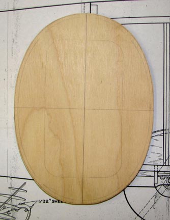
My friend Jerry Burk used his band saw to cut out
the 1/4" plywood firewall shown below for me.
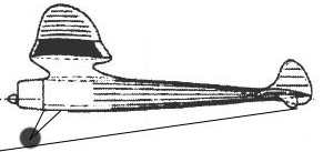
If you recall, I decided to build the Sailplane
with a two-wheel landing gear which has a double strut as shown below.
The aft wire strut will be made of 1/8" piano
wire and structure for the bottom of the fuselage has to be provided to
anchor this wire. One further condition is that I want the entire wire
landing gear removable. I will refer to this anchor as the retaining member
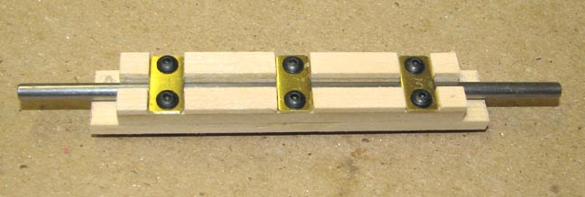
and it was made out of spruce as shown below. The bottom member is 1/8" X
1/2" spruce. I glued two 1/8" X 3/16" spruce strips to the top, leaving a
1/8" square slot down the center. I cut three 1/4" wide brass strips and
attached them to the retaining member using two 2-56 cap screws in each.
Then I glued 1/16" X 3/16" spruce pieces between the brass straps and the
ends. The picture below shows the completed spruce retaining member with a
piece of 1/8" piano wire in the slot. Notice the brass straps are numbered 1
through 3 from left to right.
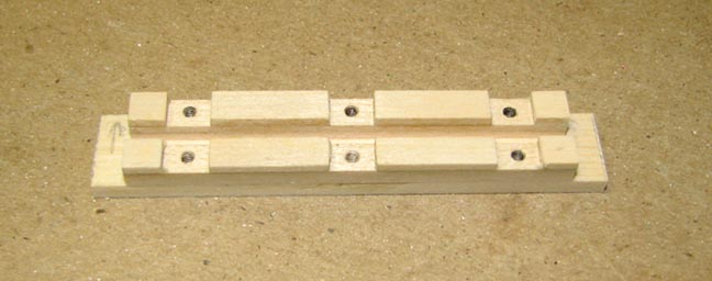
This shows the spruce retaining member with
brass straps and 1/8" wire removed. 6 holes that were drilled with a No. 50
drill bit and threaded with a 2-56 tap to receive the six 2-56 cap screws.
Notice the 3/16" overhang on each that will be glued onto the top of the
bottom longeron.
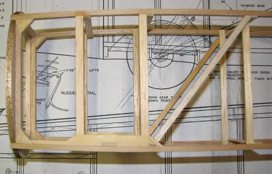
3/16" spruce doublers were incorporated on top of
the bottom longeron to trap the 3/16" overhang on the retaining member in
place as shown in the side view below. Some additional structure has also
been added.
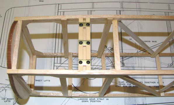
This is a bottom view showing the completed
retaining member in place.
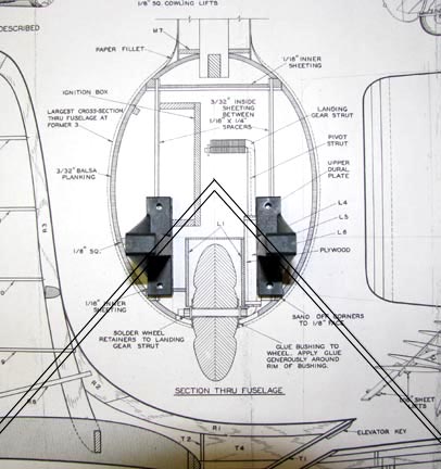
Next I laid out the locations of a set of
Goldberg composite T-mount's and the 5/32" piano wire landing gear front
strut on the firewall view of the Sailplane plan as shown below. The
vertical location shown for the landing gear is dictated by a number of
constraints including the fuel tank.
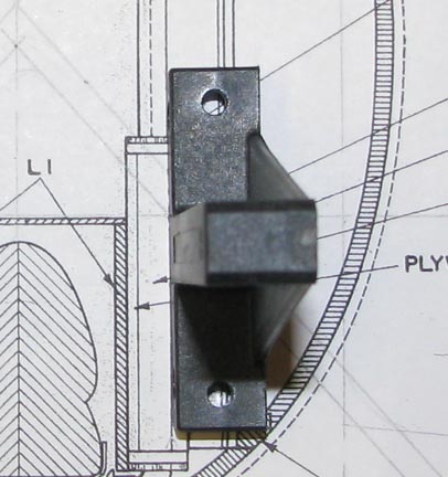
The picture below shows a close up of the right
T-mount looking aft and where the 5/32" piano wire landing gear front strut
has to pass behind it. As you can see, the 1/4" aluminum spacers that
go between the firewall and the T-mounts for the SP will require a 5/32"
slot machined out the back at angle in order to trap the landing gear wire
between the aluminum spacer and the firewall. Two additional metal straps
will be used on either side of the wire's apex to further secure it to the
firewall. I am having some second thoughts about the 5/32" front strut wire.
It very well may be that 1/8" is plenty strong enough. What do you think?
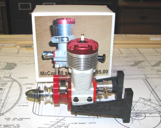
Here is the Series 20 McCoy 60 mounted on the
Carl Goldberg composite T-Mounts. I have a 2-1/4 oz metal fuel tank ordered
from Brodak that hopefully will be here by tomorrow. I want to solder
flanges on the tank and mount it behind the engine to double check the
T-Mount location on the firewall before I drill the holes in the firewall.
By the way, notice the short prop drive spool and Woody Bartelt's steel
spinner nut on the engine.................Tandy