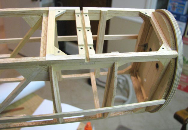
Monday, I started working on the Sailplane's
bottom forward hatch located right behind the firewall for the removal of
the ignition unit. The picture below shows the four 1/8" plywood triangles
glued in the corners of the hatch opening. These are drilled and threaded
with 2-56 threads for retention of the hatch cover. Notice that the hatch
opening extends aft beyond the rear landing gear strut slot in order to
permit the landing gear to be completely removable. One other thing to point
out is that I added additional very thin wood to the bottom of the curved
longerons to make them flat for the hatch cover interface.
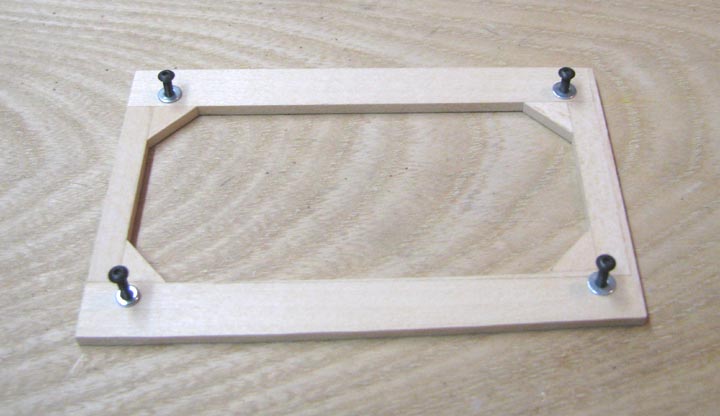
The frame of the hatch cover is shown below. It
is made out of 1/8" thick bass wood and reinforced in the four corners. Four
holes were located (to be discussed
later) and drilled out for the four 2-56 cap screws as
shown below.
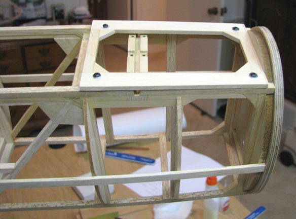
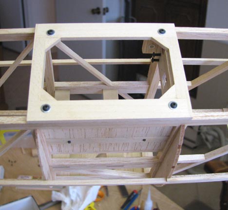
This picture was taken on Tuesday and shows the
frame of the ignition hatch cover secured to hatch opening with the four
2-56 cap screws. Later the cover will be completed by adding bulkhead pieces
and planking to the frame of the hatch cover.
Tuesday evening I started working on the
Sailplane's bottom aft hatch for access to the radio equipment. Even though
the same procedure was used as described above, I decided to document the
method I use to transfer the hole pattern from the fuselage to the radio
hatch cover frame, since I did not do this in the discussion above. I know
that there is a risk of being too tutorial, but maybe this discussion will
help some less experienced modelers.
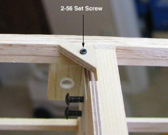
The picture below shows one of the small 2-56 set
screw I purchased from Micro Fastener.
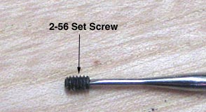
The set screw is screwed into the threaded hole
of one of the 1/8" plywood triangles glued in the corners of the radio hatch
opening as shown below. Notice that the set screw is left sticking out above
the plywood triangle about a 1/32".
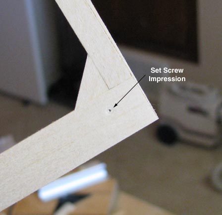
The frame of the radio hatch cover is centered
over the hatch opening and pressed down onto the raised set screw, which
leaves a slight circular impression on the cover. If you look very close,
you can see the circular impression. The center of the impression is marked
with a pencil and then a sharp punch is pushed into the pencil mark for
drilling as shown below.
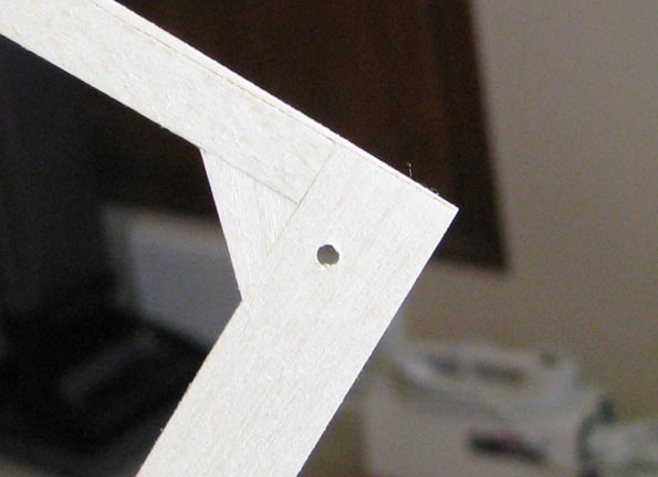
The frame of the radio hatch cover is then placed
in the drill press and a No. 44 drill bit is used to drill out the hole for
the 2-56 cap screw as shown below.
To complete the discussion, the set screw is then
moved to another 1/8" plywood triangle and screwed into its threaded hole.
The frame of the radio hatch cover is attached to the fuselage with a 2-56
cap screw, aligned with hatch opening, and again the frame pressed down onto
the raised set screw leaving a circular impression on the cover, which is
then drilled out. This process is continued until all four holes have been
transferred and drilled in the radio cover's frame as shown below.
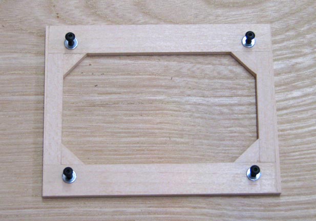
This picture before lunch today shows the frame
of the radio hatch cover secured to hatch opening with the four 2-56 cap
screws. Later the radio hatch cover will be completed by adding bulkhead
pieces and planking to the frame of the hatch cover.
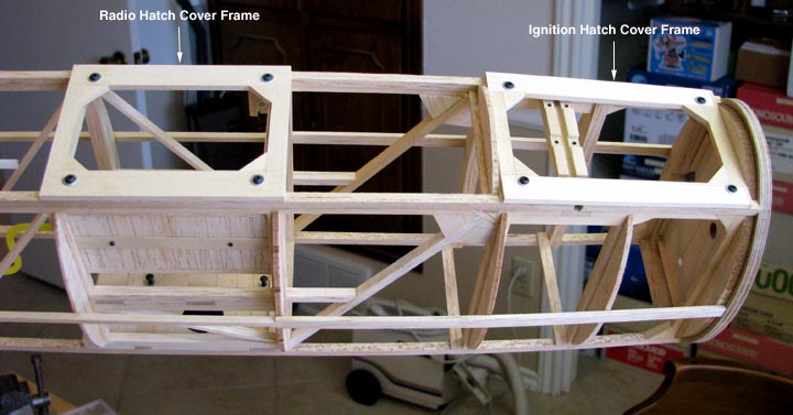
The picture below shows both hatch cover frames
attached to the fuselage.
At this point in the Sailplane's construction, I
have to discontinue the project, put away my tools, and clean up the model
room. We started the regiment of the pre-op eye drops yesterday in
preparation for cataract surgery on my left eye, which is scheduled for
11:30 a.m. in the morning. Therefore, this construction report may be my
last one for a while, depending upon the time it takes for my vision to
recover. However, I will be thinking about what needs to be done next and I
will start on the project again as soon as my vision will permit me go back
to work........................Tandy